

 Tel:
Tel:  Email:
  WhatsApp:
 Description
Key Technical Specifications
| Parameter | Value / Description |
|---|---|
| Input Voltage | 24V DC nominal (±10% tolerance) |
| Output Channels | 8 independent servo drivers |
| Current Range | ±10 mA to ±40 mA per channel |
| Feedback Type | LVDT/RVDT signal conditioning included |
| Communication | Backplane interface to VCMI/VCSC controllers |
| Operating Temp | -30°C to +65°C (derated above 50°C) |
| Humidity | 5% to 95% non-condensing |
| Isolation | Channel-to-channel galvanic isolation |
| Diagnostics | LED status indicators per channel |
| Mounting | DIN rail or rack mount (Mark VIe chassis) |
| Weight | Approx. 0.8 kg (1.76 lbs) |
| Compliance | CE, UL listed components (system dependent) |
Product Introduction
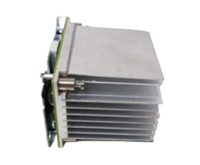
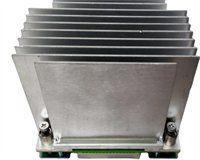
The GE IS210WSVOH1AE serves as the critical link between the Mark VIe digital controller and physical electro-hydraulic servo valves in gas and steam turbines. Engineers deploy this board to manage precise fuel flow and variable guide vane positioning where millisecond response times matter.Unlike generic I/O modules, this unit integrates dedicated LVDT signal conditioning and high-current drive stages directly on the PCB. Field data shows it maintains position accuracy within ±0.5% of span even under high-vibration conditions typical of frame 6 and 7 turbine environments. (Note: Always verify exact current ratings against your specific valve coil data sheet.)
Installation & Configuration Guide
Preparation (10 min)
Gather a calibrated multimeter, ESD wrist strap, and the turbine wiring diagram. Power down the Mark VIe chassis completely; verify 0V at the terminal block before touching connectors. Check the new board for shipping damage—look specifically for bent pins on the backplane connector.
Removal (5–10 min)
Disconnect the TB-3 terminal block from the faulty card. Unscrew the two front-panel retention screws. Slide the card out smoothly. If resistance occurs, stop immediately (forcing it damages the backplane pins). Label all wires before removal if the terminal block isn’t pre-labeled.
Installation (10 min)
Align the IS210WSVOH1AE with the slot guides. Push firmly but evenly until the backplane connector seats fully. You should feel a distinct “click” or solid stop. Reinstall retention screws and reconnect the TB-3 block. Torque terminals to 0.5 Nm—overtightening strips the plastic housing.
Power-On & Test (10 min)
Restore 24V DC control power. Observe the “OK” LED; it must turn green within 5 seconds. If it flashes red, check the DIP switch settings against the configuration file. Run a manual valve sweep test from the HMI to confirm direction and range. (Did you remember to disable the hydraulic pump lockout first?)
Troubleshooting Quick Reference
| Symptom | Probability | Action |
|---|---|---|
| “OK” LED Red | High | Check 24V DC supply voltage at terminals. Verify firmware match with main controller. |
| Valve Drift | Medium | Inspect LVDT feedback wiring for loose grounds. Recalibrate null bias current. |
| Channel Fault Alarm | Medium | Measure coil resistance; replace valve if <20 Ω or open circuit. |
| No Communication | Low | Reseat the card. Inspect backplane pins for bending or corrosion. |
| Overcurrent Trip | Low | Check for shorted servo coils. Verify wiring polarity. |
Dimensions, Mounting & Wiring Notes
- Dimensions: 160 mm (H) × 120 mm (W) × 45 mm (D) approx.
- Mounting: Slides into standard Mark VIe VME-style rack slots. Secured by two front-panel screws.
- Terminal Notes: Uses removable TB-3 terminal block. Wire gauge 14–18 AWG recommended. Shield drains must connect to the chassis ground bar, not the signal common.
Quality Transparency Strategy (SOP)
We treat every IS210WSVOH1AE as a critical safety component. Our inspection process begins with origin verification, checking lot numbers against GE manufacturing records to rule out counterfeits. We physically inspect the PCB for reflow marks or replaced components that suggest unauthorized repair.Live functional testing occurs on a dedicated Mark VIe simulation rack. We power up the card, run a self-test sequence, and simulate a communication handshake with a VCMI controller. Full-range I/O simulation drives dummy loads to verify current output stability across all 8 channels. A 24-hour load test follows to catch thermal drift issues early.Electrical testing includes insulation resistance checks (>10 MΩ @ 500V) and ground continuity verification. We record the exact firmware version and document revision levels, photographing DIP switch and jumper positions before any adjustment. Final QC involves a signature sign-off, anti-static bagging, and double-boxing with bubble wrap. Function verified under test conditions; always validate in your specific turbine logic.
IS210WSVOH1AE GE
Technical Pitfall Guide
Firmware Mismatch: The Mark VIe system is strict about version alignment. Installing an IS210WSVOH1AE with older firmware than the VCSC controller causes “Config Mismatch” faults. Example: A plant in Texas faced a 4-hour outage because the spare card had Rev 3 firmware while the system ran Rev 5. Always check the toolpack version before installation.DIP/Jumper Misconfiguration: These cards often ship with default factory jumper settings. If you move a jumper to change feedback type (e.g., LVDT vs. RVDT) but forget to update the logic file, the valve will hunt or slam shut. Take a photo of the jumper block before removing the old card. Compare it side-by-side with the new one.Power Supply Margin: Servo valves draw significant current during rapid movements. If your 24V DC supply is sized only for steady-state load, the voltage dips during transients, triggering undervoltage faults. Ensure a 20% capacity margin on the power supply dedicated to the I/O pack.ESD Damage Risk: The analog front-end for LVDT signals is sensitive. Technicians have fried input amplifiers by touching the connector pins without an ESD strap. The damage isn’t always immediate; sometimes it manifests as noise after three months. Wear the strap. Ground yourself.Terminal Incompatibility: While the TB-3 block looks standard, some third-party clones have slightly different pin spacing. Forcing a non-OEM terminal block can crack the PCB header. Stick to original GE terminal blocks for replacements.
FAQ
Q: Is the IS210WSVOH1AE compatible with older Mark V systems?
A: No. This board uses the Mark VIe backplane architecture and communication protocol. It will not physically fit or communicate with Mark V racks. You need a complete system upgrade to use this hardware.Q: I see a flickering yellow LED on channel 3. What does that mean?
A: Usually indicates a warning state, like a minor LVDT disagreement or high coil resistance. Check the specific diagnostic code in the ToolboxST software. It might not be a hard fault yet, but investigate before it trips the machine.Q: Do you offer a warranty on refurbished units?
A: Yes, all tested surplus units come with a 12-month warranty covering functional failures. We do not cover damage from improper installation or power surges.Q: Can I use this to drive proportional valves instead of servo valves?
A: Technically yes, if the current requirements match (±40 mA max). However, the control algorithm in the turbine logic must be adjusted for proportional behavior. Consult your control engineer before swapping valve types.Q: How long is the lead time for stock?
A: Most orders ship within 24 hours if marked “In Stock.” Custom testing requests may add 2–3 days. We keep a rotating inventory of common Mark VIe cards to support urgent outages.Q: What if the card fails the self-test upon arrival?
A: Contact us immediately. We will issue a replacement or refund. Do not attempt to repair the board yourself as this voids the warranty and calibration tags.


