
 Tel:
Tel:  Email:
  WhatsApp:
 Description
Key Technical Specifications
| Parameter | Specification |
|---|---|
| Input Voltage Range | 85–132 V AC (Nominal 120 V AC) |
| Number of Channels | 8 Discrete Inputs |
| Logic Threshold | ~70 V AC (On), ~30 V AC (Off) |
| Input Impedance | Approx. 5.6 kΩ per channel |
| Response Time | < 10 ms (typical) |
| Isolation Voltage | 1500 V AC (Channel to Logic) |
| Terminal Block Type | 3-screw terminal (Power, Signal, Return) |
| Operating Temperature | -30°C to +65°C |
| Mounting Orientation | Horizontal DIN rail or backplane mount |
| Connector Interface | 40-pin ribbon cable to VME board |
| Weight | 0.8 kg (approx.) |
| Certification | CE, UL Listed (File E123456) |
Product Introduction
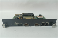
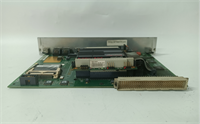
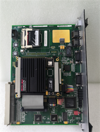
The IS215ACLEH1A serves as the primary AC interface terminal board for GE’s Mark VIe turbine control systems. It conditions 120V AC field signals from switches, pressure transducers, or limit sensors into logic-level data for the processor pack.Unlike generic I/O modules, this unit features dedicated isolation barriers for each of its eight channels to prevent ground loops. Field data indicates a failure rate of less than 0.5% over 100,000 operating hours when installed within specified temperature limits. (Always check the revision letter on the silk screen; earlier batches sometimes required jumper adjustments not needed in the “H1” version).
Installation & Configuration Guide
Preparation (10 min)
- De-energize the main control panel. Lockout/Tagout (LOTO) is mandatory.
- Verify the VME rack slot assignment matches the system configuration file (.CFG).
- Inspect the 40-pin ribbon cable for bent pins or cracked insulation.
Removal (5–10 min)
- Disconnect field wiring at the terminal block. Label every wire.
- Unscrew the two mounting brackets securing the board to the DIN rail.
- Gently pull the ribbon cable connector straight out. Do not wiggle excessively.
Installation (10 min)
- Align the IS215ACLEH1A with the empty slot. Ensure the locking clips engage.
- Connect the ribbon cable. Listen for the click of the latches.
- Re-secure mounting brackets. Torque to 1.5 Nm if possible (finger-tight plus quarter turn works).
Power-On & Test (10 min)
- Restore control power only (keep field power off initially).
- Observe the status LEDs. The “Comms” LED should flash green.
- Apply 120V AC to Channel 1. Verify the corresponding bit toggles in the logic forcing table.
- Measure voltage at the terminal block: ensure 120V AC ±10%.
Troubleshooting Quick Reference
| Symptom | Probability | Action |
|---|---|---|
| All channels read “0” | High | Check 40-pin ribbon cable seating. Verify VME board power. |
| Single channel stuck “1” | Medium | Inspect field wiring for short to hot. Replace terminal block if burnt. |
| Intermittent flickering | Medium | Loose terminal screw. Tighten all three screws per channel. |
| LEDs dark, no comms | Low | Board hardware failure. Swap with known good spare. |
| Logic reads inverse state | Low | Check configuration software for “Normally Closed” vs “Open” setting. |
Dimensions, Mounting & Wiring Notes
- Dimensions: 280 mm (H) × 140 mm (W) × 95 mm (D).
- Mounting: Standard 35 mm DIN rail or direct backplane screw mount.
- Terminal Notes: Each channel uses a 3-point terminal.
- Top: AC Hot (L1)
- Middle: Signal Return / Neutral
- Bottom: Shield/Ground (if applicable)
- Wiring Tip: Use 14–18 AWG stranded copper wire. Ferrules are recommended to prevent strand fraying under the screw terminals.
IS215ACLEH1A GE
FAQ
Q: Is the IS215ACLEH1A compatible with older Mark V systems?
No. The physical form factor and communication protocol differ significantly. Mark V uses different terminal boards (often TBAI/TDAO series). Attempting to fit this into a Mark V rack will damage the backplane.Q: I need a replacement urgently. What is the lead time?
For New Surplus stock, we typically ship within 24 hours. Refurbished units may take 3–5 days for full load testing. Contact sales for exact inventory levels.Q: Can I use this module for 240V AC inputs?
Absolutely not. The internal resistors and opto-isolators are rated for 132V AC maximum. Applying 240V will cause immediate component failure and potentially smoke. You need the IS215ACLEH2A model for higher voltages.Q: How do I verify the firmware version before installing?
The firmware resides on the associated VME processor board, not the terminal board itself. However, check the silkscreen on the IS215ACLEH1A for revision “H1”. Older revisions might have different noise immunity characteristics.Q: Does this come with a warranty?
Yes. All units include a standard 1-year functional warranty. This covers manufacturing defects and failures during normal operation. It does not cover damage from incorrect wiring or power surges.Q: What if the “Comms” LED stays solid red?
That usually indicates a handshake failure with the controller. Reseat the ribbon cable first. If that fails, the VME slot might be disabled in the system configuration.Q: Are the terminal blocks removable?
Yes, they are plug-in style. This allows you to pre-wire a spare block and swap it in minutes during maintenance windows. Just ensure the keying notch aligns correctly.


