
 Tel:
Tel:  Email:
  WhatsApp:
 Description
Key Technical Specifications
| Parameter | Value / Description |
|---|---|
| Input Channels | 16 independent analog inputs |
| Signal Type | 4-20 mA current loop (supports HART protocol) |
| Loop Power | 24V DC provided per channel (configurable) |
| Resolution | 16-bit analog-to-digital conversion |
| Isolation | Channel-to-channel and channel-to-ground isolation |
| Input Impedance | 50 Ω typical (with loop power enabled) |
| Accuracy | ±0.1% of full scale at 25°C |
| Operating Temp | -30°C to +65°C |
| Communication | Backplane interface to VCMI/VCSC controllers |
| Diagnostics | Per-channel LED status indicators |
| Update Rate | Configurable, typically 20–50 ms per scan |
| Compliance | CE, UL listed components (system dependent) |
Product Introduction
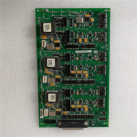
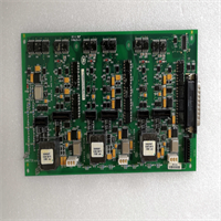
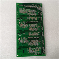
The GE IS210AEBIH3BEC is a high-density analog input module designed for the Mark VIe control platform, specifically engineered to handle 4-20 mA process signals with embedded HART diagnostic capabilities. Plant operators use this board to monitor critical parameters like bearing temperatures, pressure transmitters, and valve positions without needing separate HART multiplexers.This revision (Rev C) improves noise immunity and reduces channel crosstalk compared to earlier versions, ensuring signal stability in electrically noisy turbine halls. Field reports indicate it maintains specified accuracy even when ambient temperatures fluctuate rapidly near exhaust frames. (Make sure your system firmware supports HART passthrough before enabling advanced diagnostics.)
Installation & Configuration Guide
Preparation (10 min)
Collect a multimeter, ESD wrist strap, and the latest I/O configuration file. Shut down the Mark VIe chassis power; verify 0V DC at the rack power terminals. Inspect the new IS210AEBIH3BEC for bent backplane pins or damaged terminal blocks. Ensure you have the correct TB-3 terminal block for analog wiring.
Removal (5–10 min)
Unplug the terminal block from the existing card. Remove the two front-panel mounting screws. Slide the faulty card out gently. If it sticks, check for obstructions—do not force it. Label wires if the terminal block lacks clear markings.
Installation (10 min)
Align the new board with the rack guides. Push evenly until the backplane connector seats fully. You should feel a firm stop. Secure with the two front screws. Reattach the terminal block, ensuring wire strands are not pinched. Torque terminals to 0.5 Nm. (Over-torquing cracks the terminal housing, leading to intermittent faults.)
Power-On & Test (10 min)
Apply 24V DC control power. Watch the “OK” LED; it should turn solid green within 5 seconds. If it flashes, verify the DIP switch settings match the system configuration. Use a loop calibrator to inject a 4 mA and 20 mA signal on one channel; verify readings in the ToolboxST software. Check HART communication status if applicable.
Troubleshooting Quick Reference
| Symptom | Probability | Action |
|---|---|---|
| “OK” LED Flashing Red | High | Check 24V DC supply. Verify firmware compatibility with main controller. |
| All Channels Read Zero | Medium | Confirm loop power is enabled in configuration. Check fuse on board (if applicable). |
| Single Channel Noise | Medium | Inspect shield grounding. Ensure shield is grounded at one end only. |
| HART Communication Fail | Low | Verify device address and polling rate. Check for conflicting HART masters. |
| High Temperature Alarm | Low | Check cabinet cooling fans. Ensure airflow around the card is not blocked. |
Dimensions, Mounting & Wiring Notes
- Dimensions: 160 mm (H) × 120 mm (W) × 45 mm (D) approx.
- Mounting: Slides into standard Mark VIe VME-style rack slots. Secured by two front-panel screws.
- Terminal Notes: Uses removable TB-3 terminal block. Wire gauge 14–18 AWG recommended. Shield drains must connect to the chassis ground bar, not the signal common, to prevent ground loops.
Quality Transparency Strategy (SOP)
Every IS210AEBIH3BEC undergoes strict incoming inspection. We verify origin by checking lot numbers against GE databases to eliminate counterfeit risks. Physical inspection looks for reflow marks, replaced components, or corrosion that suggests field abuse. Accessories like terminal blocks are verified for authenticity.Live functional testing happens on a dedicated Mark VIe test rack. We power up the card, execute a self-test, and establish a communication handshake with a VCMI controller. We simulate full-range 4-20 mA signals on all 16 channels to verify linearity and HART response. A 24-hour load test runs to identify thermal drift or intermittent connections.Electrical testing includes insulation resistance checks (>10 MΩ @ 500V) and ground continuity verification. We record the exact firmware version and document revision levels, photographing DIP switch and jumper positions before any adjustment. Final QC involves a signature sign-off, anti-static bagging, and double-boxing with bubble wrap. Function verified under test conditions; always validate in your specific turbine logic.
IS210AEBIH3BEC GE
Technical Pitfall Guide
Firmware Mismatch: The Mark VIe system requires strict firmware alignment between I/O boards and the main controller. Installing an IS210AEBIH3BEC with older firmware than the VCSC controller causes “Config Mismatch” faults. Example: A facility in Ohio faced a 6-hour delay because the spare card had Rev B firmware while the system ran Rev D. Always check the toolpack version before installation.DIP/Jumper Misconfiguration: These cards often ship with default factory jumper settings for loop power. If you need external loop power but forget to move the jumper, the transmitter won’t energize, and you’ll read zero. Take a photo of the jumper block before removing the old card. Compare it side-by-side with the new one.Power Supply Margin: While individual channels draw little current, 16 active loops add up. If your 24V DC supply is undersized, voltage drops during simultaneous transients can cause erratic readings. Ensure a 20% capacity margin on the power supply dedicated to the I/O pack.ESD Damage Risk: The analog input circuitry is sensitive to electrostatic discharge. Technicians have damaged input amplifiers by touching connector pins without an ESD strap. The damage might not be immediate; sometimes it appears as increased noise after weeks of operation. Wear the strap. Ground yourself.Ground Loop Issues: Improper shielding causes significant noise on analog signals. Connecting shields at both the field device and the cabinet end creates a ground loop. Always ground the shield at the cabinet end only. Isolate the field end.
FAQ
Q: Can I mix HART and non-HART devices on this same board?
A: Yes, the IS210AEBIH3BEC handles both. You just need to configure the HART enable setting per channel in the ToolboxST software. Non-HART channels work as standard 4-20 mA inputs.Q: My “OK” LED is green, but I see no data in the HMI. What’s wrong?
A: Likely a configuration mismatch or communication timeout. Check if the controller recognizes the card in the hardware config tree. Sometimes a simple reboot of the controller clears the handshake error.Q: Do you provide a calibration certificate with refurbished units?
A: We provide a functional test report showing pass/fail status for all channels. We do not provide NIST-traceable calibration certificates unless specifically requested as a paid add-on service.Q: Is this card compatible with the Mark V system?
A: No. This board uses the Mark VIe backplane architecture and communication protocol. It will not physically fit or communicate with Mark V racks. You need a complete system upgrade to use this hardware.Q: How quickly can you ship a replacement?
A: Most orders ship within 24 hours if marked “In Stock.” Custom testing requests may add 2–3 days. We keep a rotating inventory of common Mark VIe cards to support urgent outages.Q: What happens if I plug in a 24V source into an input channel by mistake?
A: The board has some protection, but high voltage can blow the internal fuse or damage the input circuitry. Always double-check your wiring before applying power. If it happens, test the channel with a calibrator before putting it back in service.


