 Tel:
Tel:  Email:
  WhatsApp:
 Description
Key Technical Specifications
- Input Voltage: 24V DC nominal (±15% tolerance for legacy systems)
- Signal Type: Discrete Digital Inputs, TC (Thermocouple) or RTD interfaces (config dependent)
- Channel Count: Typically 16–24 discrete channels per pack
- Communication Protocol: Proprietary Mark V Serial / IONet
- Operating Temp: -20°C to +60°C (Derate above 50°C)
- Isolation: Optical isolation on digital inputs (2.5kV)
- Connector Type: 50-pin or 64-pin DIN41612 style backplane
- LED Indicators: Fault (Red), Active (Green), Comm (Yellow)
- Mounting: Vertical slot in Mark V rack (VCMI/TCE backplane)
- Firmware Storage: On-board EPROM chips (non-volatile, non-flash)
- Certification: Original GE Manufacturing Standards (Pre-CE era typical)
- Weight: Approx. 0.6 kg (1.32 lbs)
Product Introduction
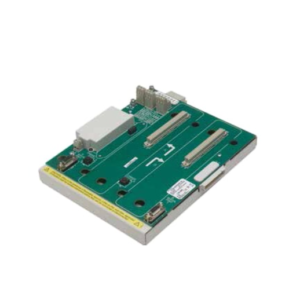
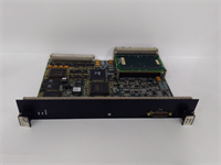
The GE IS200VTURH2BAC is a specialized I/O pack designed exclusively for the GE Mark V Speedtronic turbine control system. It acts as the primary bridge between critical turbine sensors (speed probes, thermocouples) and the Triple Modular Redundant (TMR) processors. This module is essential for maintaining safe operation in legacy Frame 5 and 6 gas turbines globally.While newer Mark VIe systems use Ethernet, this unit relies on robust, time-tested serial communication protocols proven over 30+ years of field service. Its design prioritizes noise immunity in high-interference turbine environments. Field records show these units often exceed 20 years of service life, provided the cooling fans in the control cabinet remain functional and dust levels are managed.
Installation & Configuration Guide
Phase 1: Preparation (10 min)
- Identify the exact slot location in the Mark V rack (e.g., Slot 4 in TCEA).
- Crucial Step: Photograph the EPROM chip labels on the failing unit. The revision code (e.g., “A”, “B”, “C”) must match exactly.
- Power down the specific controller lane if possible. If running in TMR, ensure the other two lanes are healthy before pulling one.
- Don anti-static wrist strap. Mark V logic cards are extremely ESD sensitive.
Phase 2: Removal (5–10 min)
- Disconnect any external ribbon cables if present (rare for VTUR, usually backplane only).
- Unscrew the two captive mounting screws at the top and bottom of the faceplate.
- Use the extraction tool (or gently rock by the faceplate edges) to pull the card straight out.
- Warning: Do not touch the gold pins on the backplane connector. Oils from skin cause corrosion over time.
Phase 3: Installation (10 min)
- Compare the new IS200VTURH2BAC physically with the old one. Check jumper settings (W1, W2, etc.)—these are often set for specific voltage ranges.
- Align the card guides in the rack. Slide the card in firmly but smoothly until the backplane connector seats. You should feel even resistance, then a stop.
- Tighten the mounting screws. Loose cards cause intermittent “Comm Loss” alarms during vibration.
- Re-attach any ribbon cables, ensuring Pin 1 alignment (usually marked with a red stripe).
Phase 4: Power-On & Test (10 min)
- Restore power to the controller lane.
- Watch the LED sequence. The “Active” green LED should stabilize within 10 seconds.
- Check the HMI (Operator Interface) for “I/O Fault” clearances.
- If the “Fault” LED remains red, immediately power down and re-check the EPROM version. A mismatch here prevents the TCE processor from recognizing the card type.
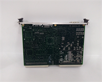
IS200VTURH2BAC GE
Troubleshooting Quick Reference
| Symptom | Probability | Action |
|---|---|---|
| Solid Red Fault LED | High | EPROM version mismatch or bad backplane contact. Reseat card. |
| No LEDs lit | High | 24V DC supply missing to the rack or blown fuse on the power distribution board. |
| “Comm Fail” Alarm | Medium | Dirty backplane pins. Clean with contact cleaner and reseating. |
| Erratic Trip Signals | Low | Loose terminal screw or failing optical isolator inside the pack. |
| Card Gets Very Hot | Low | Internal short circuit. Replace immediately; do not run. |
Dimensions, Mounting & Wiring Notes
- Dimensions: Approx. 133mm (H) x 100mm (W) x 40mm (D) – Standard Eurocard form factor variant.
- Mounting: Vertical insertion into Mark V TCE/TCR chassis slots. Secured by two front-panel screws.
- Terminal Notes: Most VTUR packs connect via the backplane only; external wiring goes to the terminal board (TB) which then plugs into the pack via ribbon cable. Ensure ribbon cable locks are engaged. A loose ribbon cable is the #1 cause of “ghost” trips we see in the field.
FAQ
Q: Can I upgrade this to a newer revision like IS200VTURH2CAC?
A: Maybe, but it requires a full logic download and potentially a controller reboot. The “BAC” revision has specific timing characteristics. Swapping revisions without updating the controller’s configuration database will likely cause a trip.Q: Why is the EPROM version so important?
A: Mark V controllers hard-check the I/O pack type and revision during boot. If the software expects “Rev B” and finds “Rev C,” it flags a hardware mismatch and may shut down that control lane for safety.Q: Is this part still made by GE?
A: No, the Mark V system is obsolete. All available stock is either New Surplus (old stock found in warehouses) or Refurbished. We test all refurbished units extensively.Q: My card works but the LED flickers. Is that normal?
A: No. The Active LED should be solid. Flickering indicates a marginal power connection or a failing component on the 5V logic rail. Plan for replacement soon.Q: How long does shipping take for a tested unit?
A: Since these are stocked items for legacy support, we typically ship within 24 hours. International express takes 2–4 days.Q: I don’t have the EPROM reader. How can I check the version?
A: You don’t need a reader. Just look at the white sticker on the black square chip on the card face. It will say something like “27C256-15” followed by a handwritten or printed revision code. Match that code.
Quality Transparency Strategy (SOP)
1. Incoming Inspection
- Origin Verification: Validate GE part number formatting and font consistency on labels (counterfeits often use wrong fonts).
- Anti-Counterfeit Check: Inspect solder joints under magnification. Look for “reflow” signs indicating previous cheap repairs.
- Physical Inspection: Check for bent backplane pins—a common issue with removed cards.
- Accessories Verification: Ensure ribbon cable connectors are intact and not cracked.
2. Live Functional Testing
- Test Rack: Unit inserted into a verified working Mark V TCE simulator rack.
- Power-On Self-Test: Monitor boot handshake with the TCE processor.
- Communication Handshake: Verify the controller recognizes the specific “VTUR” ID.
- Full-Range I/O Simulation: Inject simulated speed pulses and thermocouple mV signals to verify channel response.
- 24h Load Test: Run continuous pulse simulation to detect thermal drift.
- Report: Generate test log showing channel pass/fail status.
3. Electrical Testing
- Insulation Resistance: >10 MΩ @ 250V DC (Lower voltage used for legacy electronics safety).
- Ground Continuity: Chassis ground path <0.1 Ω.
- Hi-Pot: Skipped for legacy EPROM boards to avoid damaging old insulation.
4. Firmware Verification
- Version Record: Visually record and photograph all EPROM chip codes.
- Checksum Verification: If equipment allows, read checksum to ensure data integrity.
- Photo Record: Document jumper positions (W1-W10) before resetting.
5. Final QC & Packaging
- QC Signature: Senior technician sign-off on legacy compatibility.
- Anti-Static: Sealed in pink anti-static foam and bag.
- Packaging: Rigid box with extra corner protection for backplane pins.
- Labeling: “Legacy Verified” label with test date.
- Disclaimer: Function verified under test conditions. Site-specific logic compatibility is the integrator’s responsibility.
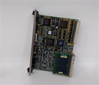
IS200VTURH2BAC GE
Technical Pitfall Guide
EPROM Version Mismatch
- Scenario: A maintenance team installs a “newer” looking card (Rev C) to replace a failed Rev B. The turbine starts, runs for 10 seconds, then trips on “Hardware Mismatch.”
- Fix: Always match the revision letter exactly. If upgrading, coordinate with the control engineer to update the TCE logic first.
Backplane Pin Damage
- Risk: Forcing the card in misaligned bends the delicate 0.1″ pitch pins.
- Action: Use a flashlight to inspect the rack slot before insertion. If pins are bent, use a dental pick to straighten them before inserting the card. Never force it.
Ribbon Cable Orientation
- Issue: Plugging the ribbon cable in upside down (Pin 1 to Pin 64).
- Result: Immediate destruction of input buffers.
- Prevention: Look for the red stripe on the cable and the “1” marker on the connector. They must align.
Cooling Airflow Neglect
- Detail: Mark V racks rely on specific airflow direction. Blocking vents with new cabling raises internal temps.
- Consequence: Legacy capacitors dry out faster, leading to premature failure. Keep cable dress neat and away from fan intakes.
ESD Sensitivity
- Warning: These boards pre-date modern ESD hardening. A simple static shock from walking on carpet can destroy the CPU interface chip.
- Real-world detail: If you hear a “snap” or feel a tingle when touching the card edge, stop. Ground yourself on the unpainted rack rail for 10 seconds before proceeding. The smell of ozone means damage has already occurred.