 Tel:
Tel:  Email:
  WhatsApp:
 Description
Key Technical Specifications
| Parameter | Value / Description |
|---|---|
| Input Channels | 24 independent universal temperature inputs |
| Sensor Types | RTD (2/3-wire Pt100, Pt1000, Ni120) & Thermocouple (J, K, E, N, T, R, S, B) |
| Excitation Current | Configurable per channel (typically 1 mA for RTDs) |
| Resolution | 16-bit analog-to-digital conversion |
| Isolation | Channel-to-channel and channel-to-ground isolation (500V) |
| Accuracy | ±0.1% of reading + 0.2°C (RTD); ±0.2% + 1°C (TC) |
| Cold Junction Comp | Automatic internal CJC for thermocouples |
| Operating Temp | -30°C to +65°C |
| Communication | Backplane interface to VCMI/VCSC controllers |
| Diagnostics | Per-channel open/short detection, LED status indicators |
| Update Rate | Configurable, typically 50–100 ms per scan |
| Compliance | CE, UL listed components (system dependent) |
Product Introduction
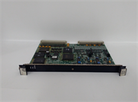
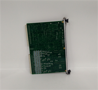
The GE IS200VRTDH1D is a versatile temperature input module for the Mark VIe control platform, designed to monitor up to 24 critical temperature points using either RTDs or thermocouples. Turbine engineers rely on this board to track exhaust spread, bearing metal temperatures, and cooling air profiles with high precision.This “D” revision enhances noise rejection and improves cold junction compensation stability compared to earlier “A” or “C” versions, reducing false trip risks during grid disturbances. Field experience shows it maintains specified accuracy even when cabinet ambient temperatures swing by 15°C within an hour. (Note: Ensure your logic solver is configured for the specific sensor type assigned to each channel.)
Installation & Configuration Guide
Preparation (10 min)
Gather a multimeter, ESD wrist strap, and the I/O configuration database. Power down the Mark VIe chassis; verify 0V DC at the rack power terminals. Inspect the new IS200VRTDH1D for bent backplane pins. Confirm you have the correct TB-3 terminal block wired for your specific sensor types (RTD vs. TC wiring differs).
Removal (5–10 min)
Disconnect the terminal block from the faulty card. Remove the two front-panel retention screws. Slide the card out smoothly. If resistance occurs, stop immediately—forcing it damages the backplane pins. Label all wires if the terminal block isn’t pre-labeled.
Installation (10 min)
Align the IS200VRTDH1D with the slot guides. Push firmly but evenly until the backplane connector seats fully. You should feel a distinct “click” or solid stop. Reinstall retention screws and reconnect the TB-3 block. Torque terminals to 0.5 Nm. (Over-tightening strips the plastic housing, causing intermittent open-circuit alarms.)
Power-On & Test (10 min)
Restore 24V DC control power. Observe the “OK” LED; it must turn green within 5 seconds. If it flashes red, check DIP switch settings against the configuration file. Use a precision temperature calibrator to simulate a known temperature (e.g., 100°C Pt100) on one channel; verify the reading in ToolboxST. Check for “Open Circuit” alarms on unused channels.
Troubleshooting Quick Reference
| Symptom | Probability | Action |
|---|---|---|
| “OK” LED Red | High | Check 24V DC supply voltage. Verify firmware match with main controller. |
| All Channels Read Max/Min | Medium | Check sensor common wiring. Verify excitation current is enabled in config. |
| Single Channel Drift | Medium | Inspect sensor wiring for loose connections or moisture ingress. Recalibrate offset. |
| Thermocouple Noise | Low | Verify shield grounding. Ensure shield is grounded at cabinet end only. |
| CJC Error Alarm | Low | Check internal board temperature sensor. Ensure cabinet cooling is functional. |
Dimensions, Mounting & Wiring Notes
- Dimensions: 160 mm (H) × 120 mm (W) × 45 mm (D) approx.
- Mounting: Slides into standard Mark VIe VME-style rack slots. Secured by two front-panel screws.
- Terminal Notes: Uses removable TB-3 terminal block. Wire gauge 14–18 AWG recommended. For 3-wire RTDs, ensure lead resistance matching if cable runs exceed 50 meters. Shield drains must connect to the chassis ground bar.
Quality Transparency Strategy (SOP)
We treat every IS200VRTDH1D as a critical safety component. Our inspection process begins with origin verification, checking lot numbers against GE manufacturing records to rule out counterfeits. We physically inspect the PCB for reflow marks or replaced components that suggest unauthorized repair.Live functional testing occurs on a dedicated Mark VIe simulation rack. We power up the card, run a self-test sequence, and simulate a communication handshake with a VCMI controller. We inject precise resistance and voltage signals across all 24 channels to verify linearity, CJC accuracy, and open-circuit detection. A 24-hour load test follows to catch thermal drift issues early.Electrical testing includes insulation resistance checks (>10 MΩ @ 500V) and ground continuity verification. We record the exact firmware version and document revision levels, photographing DIP switch and jumper positions before any adjustment. Final QC involves a signature sign-off, anti-static bagging, and double-boxing with bubble wrap. Function verified under test conditions; always validate in your specific turbine logic.
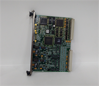
IS200VRTDH1D GE
Technical Pitfall Guide
Firmware Mismatch: The Mark VIe system is strict about version alignment. Installing an IS200VRTDH1D with older firmware than the VCSC controller causes “Config Mismatch” faults. Example: A plant in Germany faced a 5-hour outage because the spare card had Rev B firmware while the system ran Rev D. Always check the toolpack version before installation.DIP/Jumper Misconfiguration: These cards often ship with default factory jumper settings for excitation current. If you are using thermocouples but forget to disable RTD excitation, you will burn out the TC or read wildly incorrect values. Take a photo of the jumper block before removing the old card. Compare it side-by-side with the new one.Lead Resistance Errors: Long cable runs to RTDs add resistance, causing false high-temperature readings. If cables exceed 50 meters, use 3-wire configuration and verify lead balance. Some older logic files assume zero lead resistance; update your scaling factors if necessary.ESD Damage Risk: The analog front-end for low-level thermocouple signals is extremely sensitive. Technicians have fried input amplifiers by touching the connector pins without an ESD strap. The damage isn’t always immediate; sometimes it manifests as noise after three months. Wear the strap. Ground yourself.Terminal Incompatibility: While the TB-3 block looks standard, some third-party clones have slightly different pin spacing. Forcing a non-OEM terminal block can crack the PCB header. Stick to original GE terminal blocks for replacements.
FAQ
Q: Can I mix RTDs and Thermocouples on the same IS200VRTDH1D board?
A: Yes, the hardware supports mixed sensor types. However, you must configure each channel individually in the ToolboxST software to match the connected sensor. Do not mix them on the same terminal block without clear labeling.Q: My thermocouple readings are jumping by 10°C randomly. What’s wrong?
A: Likely a grounding issue or a failing cold junction compensation sensor. Check that the shield is grounded at only one end (cabinet side). Also, verify the cabinet ambient temperature is stable; if the fan failed, the CJC reference drifts.Q: Do you offer a warranty on refurbished units?
A: Yes, all tested surplus units come with a 12-month warranty covering functional failures. We do not cover damage from improper installation, lightning strikes, or power surges.Q: Is this card compatible with older Mark V systems?
A: No. This board uses the Mark VIe backplane architecture and communication protocol. It will not physically fit or communicate with Mark V racks. You need a complete system upgrade to use this hardware.Q: How long is the lead time for stock?
A: Most orders ship within 24 hours if marked “In Stock.” Custom testing requests may add 2–3 days. We keep a rotating inventory of common Mark VIe cards to support urgent outages.Q: What if the card fails the self-test upon arrival?
A: Contact us immediately. We will issue a replacement or refund. Do not attempt to repair the board yourself as this voids the warranty and calibration tags.