 Tel:
Tel:  Email:
  WhatsApp:
 Description
Key Technical Specifications
| Parameter | Value / Description |
|---|---|
| Input Channels | 8 independent vibration/position inputs |
| Sensor Type | Eddy current proximity probes (requires external or internal -24V DC) |
| Signal Range | 0 to -24 V DC (typical probe output) |
| Input Impedance | >1 MΩ (high impedance to prevent loading) |
| Bandwidth | 0.5 Hz to 10 kHz (configurable filters) |
| Resolution | 16-bit analog-to-digital conversion |
| Isolation | Channel-to-channel and channel-to-ground isolation |
| Accuracy | ±0.5% of full scale at 25°C |
| Operating Temp | -30°C to +65°C |
| Communication | Backplane interface to VCMI/VCSC controllers |
| Diagnostics | Per-channel OK/Fault LED, open/short detection |
| Update Rate | High-speed sampling (up to 1 kHz per channel) |
Product Introduction
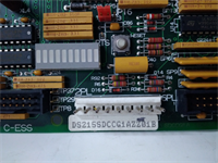
The GE IS200TVBAH2ACC is a specialized analog input module for the Mark VIe platform, engineered to interface directly with eddy current proximity probes for shaft vibration and axial position monitoring. Critical for turbine protection, this board converts raw probe voltage swings into digital values used by the overspeed and vibration trip logic.This “C” revision improves high-frequency noise rejection and stabilizes the internal signal conditioning circuitry compared to earlier “A” versions, reducing false trips during generator sync or electrical storms. Field data confirms it maintains signal integrity even when probe cables run parallel to high-voltage ignition leads. (Always verify your probe vendor compatibility; while Bently Nevada is standard, other brands may require gain adjustments.)
Installation & Configuration Guide
Preparation (10 min)
Gather a multimeter, ESD wrist strap, and the turbine protection logic diagram. Power down the Mark VIe chassis completely; verify 0V at the terminal block. Inspect the new board for bent pins on the backplane connector. Ensure you have the correct shielded coaxial cables ready for the proximitors.
Removal (5–10 min)
Disconnect the coaxial or twisted-pair cables from the TB-3 terminal block. Unscrew the two front-panel retention screws. Slide the card out smoothly. If resistance occurs, stop immediately—forcing it damages the backplane pins. Label all cables clearly before removal if not pre-tagged.
Installation (10 min)
Align the IS200TVBAH2ACC with the slot guides. Push firmly but evenly until the backplane connector seats fully. You should feel a distinct “click” or solid stop. Reinstall retention screws and reconnect the sensor cables. Torque terminals to 0.5 Nm. (Over-tightening crushes the coaxial center pin insulation, causing intermittent shorts.)
Power-On & Test (10 min)
Restore 24V DC control power. Observe the “OK” LED; it must turn green within 5 seconds. If it flashes red, check the DIP switch settings for sensor power configuration (-24V enabled/disabled). Use a proximitors simulator or a known good probe to inject a gap voltage (e.g., -10V DC); verify the reading in ToolboxST. Check for “Probe Fault” alarms.
Troubleshooting Quick Reference
| Symptom | Probability | Action |
|---|---|---|
| “OK” LED Red | High | Check 24V DC supply. Verify firmware match with main controller. |
| All Channels Read Zero | Medium | Confirm sensor power (-24V) is enabled via jumpers or external supply. Check fuse. |
| High Noise on Signal | Medium | Inspect cable shielding. Ensure shield is grounded at cabinet end only. Check for ground loops. |
| Single Channel Fault | Low | Measure probe resistance and gap voltage. Replace probe if open/shorted. |
| Drifting Baseline | Low | Check probe mounting stability. Loose mounting brackets cause false vibration readings. |
Dimensions, Mounting & Wiring Notes
- Dimensions: 160 mm (H) × 120 mm (W) × 45 mm (D) approx.
- Mounting: Slides into standard Mark VIe VME-style rack slots. Secured by two front-panel screws.
- Terminal Notes: Uses removable TB-3 terminal block. Use shielded coaxial cable (e.g., Belden 9207) for probe inputs. Shield drains must connect to the chassis ground bar, not the signal common. Keep probe cables away from VFD outputs.
Quality Transparency Strategy (SOP)
We treat every IS200TVBAH2ACC as a critical safety component. Our inspection process begins with origin verification, checking lot numbers against GE manufacturing records to rule out counterfeits. We physically inspect the PCB for reflow marks or replaced components that suggest unauthorized repair.Live functional testing occurs on a dedicated Mark VIe simulation rack equipped with a Bently Nevada probe simulator. We power up the card, run a self-test sequence, and simulate a communication handshake with a VCMI controller. We sweep input voltages from -2V to -22V across all 8 channels to verify linearity and frequency response. A 24-hour load test follows to catch thermal drift issues early.Electrical testing includes insulation resistance checks (>10 MΩ @ 500V) and ground continuity verification. We record the exact firmware version and document revision levels, photographing DIP switch and jumper positions before any adjustment. Final QC involves a signature sign-off, anti-static bagging, and double-boxing with bubble wrap. Function verified under test conditions; always validate in your specific turbine logic.
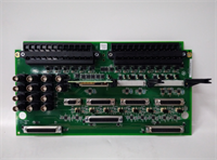
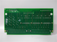
IS200TVBAH2ACC GE
Technical Pitfall Guide
Firmware Mismatch: The Mark VIe system is strict about version alignment. Installing an IS200TVBAH2ACC with older firmware than the VCSC controller causes “Config Mismatch” faults. Example: A plant in Saudi Arabia faced a 3-hour delay because the spare card had Rev A firmware while the system ran Rev C. Always check the toolpack version before installation.Jumper Misconfiguration (Sensor Power): This card can provide -24V DC to probes or accept externally powered signals. If your probes are externally powered but the card jumpers are set to “Internal Power,” you risk back-feeding voltage and damaging the card. Take a photo of the jumper block before removing the old card. Compare it side-by-side with the new one.Ground Loop Noise: Vibration signals are low-level and highly susceptible to noise. Connecting cable shields at both the probe housing and the cabinet end creates a ground loop, introducing 60Hz hum that looks like vibration. Always ground the shield at the cabinet end only. Isolate the field end.ESD Damage Risk: The input amplifiers for these high-impedance signals are extremely sensitive. Technicians have damaged channels by touching the center pins of the BNC/coax connectors without an ESD strap. The damage might not be immediate; sometimes it appears as increased noise floor after weeks of operation. Wear the strap. Ground yourself.Cable Capacitance Issues: Long cable runs (>300 feet) add capacitance, which can attenuate high-frequency vibration signals. If your cables are long, verify the system bandwidth settings in the logic. You may need to adjust the filter cutoff frequencies to avoid missing critical blade pass frequencies.
FAQ
Q: Can I use this board for velocity sensors instead of proximity probes?
A: Technically yes, if the voltage range matches (0-24V AC/DC). However, the internal filtering is optimized for eddy current signals. For velocity sensors, a generic analog input board (like the AEBI) is often preferred unless the TVBA is specifically configured for it in the logic.Q: My vibration readings show a constant 0.5 mils even when the turbine is stopped. Is this normal?
A: No, that indicates electrical noise or a grounding issue. A stopped turbine should read near zero (within ±0.1 mils). Check your shield grounding and ensure the probe tip isn’t rubbing against the shaft.Q: Do you offer a warranty on refurbished units?
A: Yes, all tested surplus units come with a 12-month warranty covering functional failures. We do not cover damage from improper installation, lightning strikes, or power surges.Q: Is this card compatible with the Mark V system?
A: No. This board uses the Mark VIe backplane architecture and communication protocol. It will not physically fit or communicate with Mark V racks. You need a complete system upgrade to use this hardware.Q: How quickly can you ship a replacement?
A: Most orders ship within 24 hours if marked “In Stock.” Custom testing requests may add 2–3 days. We keep a rotating inventory of common Mark VIe cards to support urgent outages.Q: What if the card fails the self-test upon arrival?
A: Contact us immediately. We will issue a replacement or refund. Do not attempt to repair the board yourself as this voids the warranty and calibration tags.