Tel:
Tel:  Email:
  WhatsApp:
 Description
Technical Specifications (For Spare Parts Verification)
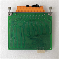
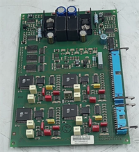
- GE Module ID: IS200TSVCH1AJE
- MRP Number: MRP081636
- Function: Servo Valve Control Terminal Board (TSVC = Terminal Servo Valve Control)
- Compatible I/O Modules: Typically paired with IS200TQBAH1Bxx (Analog Output) or IS200TVIBH1Bxx (LVDT Input) in a Mark VI I/O Pack
- Key Interfaces:
- LVDT Excitation: ±5 VAC @ 2.5–10 kHz (user-configurable via jumpers)
- Servo Valve Drive: ±50 mA or ±100 mA current output (depending on configuration)
- Position Feedback: Differential LVDT input (±10 V range)
- Field Wiring: Screw-terminal blocks for valve coils, LVDTs, and ground
- Mounting: DIN rail or chassis-mounted in remote I/O cabinet near hydraulic actuators
- Diagnostics: No onboard LEDs; faults reported via controller (e.g., “LVDT OPEN,” “SERVO CURRENT FAULT”)
- Calibration: Requires precision null/bias adjustment during commissioning using Toolbox software
- Revision Sensitivity: H1AJE includes specific filter settings, gain stages, and protection circuits—not backward-compatible with earlier revisions without revalidation
-

MRP081636 IS200TSVCH1AJE
System Role and Downtime Impact
The IS200TSVCH1AJE is a critical analog interface in turbine control loops. It translates digital commands from the Mark VI controller into precise current signals that drive electro-hydraulic servo valves—devices that modulate fuel flow, steam admission, or IGV angle in real time. Simultaneously, it reads position feedback from LVDTs (Linear Variable Differential Transformers) to close the control loop.
If this terminal board fails:
- The servo valve may stick, drift, or go full open/closed
- The controller detects LVDT signal loss or mismatch and triggers alarms like “VALVE POSITION ERROR”
- In severe cases, the turbine protection system initiates a controlled shutdown or emergency trip to prevent overspeed or thermal damage
Recovery requires replacement, re-calibration of null/bias, and loop validation—processes that typically demand a planned outage due to safety interlocks.
Reliability Analysis and Common Failure Modes
Deployed widely from the late 1990s through the 2000s, many TSVCH1AJE boards are now operating beyond their design life. Harsh environments (heat, vibration, EMI) accelerate degradation.
Common Failure Modes:
- LVDT oscillator circuit failure: Causes loss of excitation → LVDT reads zero → false “valve closed” indication
- Output op-amp or driver transistor burnout: Results in zero or saturated servo current → valve unresponsive
- Terminal block corrosion or loose wiring: Leads to intermittent feedback or coil disconnection
- Capacitor aging in filter networks: Introduces noise into position feedback, causing valve hunting or instability
Design Limitations:
- Analog components sensitive to temperature drift
- No self-diagnostics at the terminal board level
- Vulnerable to ground loops if shield grounding is improper
Preventive Maintenance Recommendations:
- Perform annual LVDT signal integrity checks (amplitude, phase, noise)
- Verify servo current output under simulated command using calibrated loads
- Inspect field wiring for insulation wear or loose screws
- Ensure proper shield termination at one end only to avoid ground loops
-
MRP081636 IS200TSVCH1AJE
Lifecycle Status and Migration Strategy
GE has fully obsoleted the IS200TSVCH1AJE along with the Mark VI platform. No repairs, firmware updates, or official support are available. Continuing to operate systems dependent on this board carries significant risk due to:
- Extremely limited verified spares
- High cost of last-time buys (often >$3,000/unit)
- Loss of calibration expertise among service providers
Short-Term Mitigation:
- Secure at least one matched spare with known calibration history
- Document all jumper settings and null/bias values for rapid recovery
- Isolate the I/O cabinet from excessive heat and electrical noise
Long-Term Path:
Migrate to Mark VIe or Mark VIe Evolution, which replaces discrete terminal boards like TSVCH with integrated VSVO (Valve Servo Output) I/O Packs featuring:
- Built-in diagnostics (LVDT health, coil resistance, current monitoring)
- Software-configurable excitation frequency and output range
- Redundant communication over Ethernet
This transition involves rewiring valve/LVDT connections to new terminal blocks and re-commissioning control loops—but eliminates single-point obsolescence and improves reliability.
Until then, a disciplined life-extension strategy—centered on validated spares, proactive calibration, and environmental control—is essential to maintain safe, stable turbine operation.