
 Tel:
Tel:  Email:
  WhatsApp:
 Description
Key Technical Specifications
| Parameter | Specification |
|---|---|
| Input/Output Type | Analog Voltage/Current (Configurable per channel) |
| Channel Count | Typically 16–24 channels (Verify label) |
| Signal Range | 4–20 mA, 0–10 V, ±10 V (Jumper selectable) |
| Supply Voltage | 24V DC (for internal circuitry and transmitters) |
| Isolation | Channel-to-ground (Check specific revision datasheet) |
| Mounting Type | Mark VIe Backplane Slot / DIN Rail |
| Operating Temp | -30°C to +65°C |
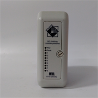
| Indicator LEDs | Power, Fault, Per-channel status (if equipped) |
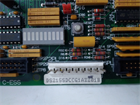
| Connector Type | 3-tier Euro-style terminal blocks |
| Wire Gauge | 18–14 AWG (Stranded) |
| Weight | Approx. 1.0 kg |
| Compliance | CE, UL (Check specific unit label) |
Product Introduction
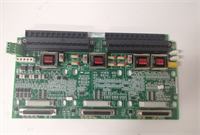
The IS200TSVCH1AJE acts as the critical bridge between field instrumentation (pressure transmitters, valve positioners) and the GE Mark VIe digital control processors, conditioning raw signals for high-speed acquisition. It consolidates wiring termination, signal scaling, and noise filtering into a single rack-mounted unit.This specific revision (“JE”) often incorporates updated protection circuitry to handle transient voltage spikes common in turbine hall environments. Field logs suggest that proper shield termination on these boards reduces signal noise by approximately 30% compared to earlier revisions lacking integrated ground buses. (Always check the jumper settings; factory defaults rarely match specific site requirements).
Installation & Configuration Guide
Preparation (10 min)
- De-energize the control cabinet. Apply Lockout/Tagout (LOTO).
- Retrieve the site-specific wiring diagram and I/O configuration file.
- Inspect the IS200TSVCH1AJE for shipping damage, specifically checking terminal block integrity.
Removal (5–10 min)
- Label all field wires before disconnecting. Use a permanent marker on the wire ferrules.
- Unscrew the terminal block retaining screws. Remove blocks if necessary for access.
- Remove mounting screws securing the board to the chassis.
- Pull the module straight out.
- Real-world detail: If the backplane connector feels gritty, do not force it. Inspect for debris or bent pins on the rack side first.
Installation (10 min)
- Align the IS200TSVCH1AJE with the correct backplane slot as per the engineering drawing.
- Seat the board firmly until the connector engages.
- Secure with mounting screws. Torque to 1.5 Nm.
- Reconnect field wiring. Ensure shield drains are bonded to the cabinet ground bar, not the signal negative.
Power-On & Test (10 min)
- Restore 24V DC control power.
- Verify the “Power” LED illuminates.
- Simulate a 4 mA and 20 mA signal (or 0V/10V) on one channel.
- Confirm the corresponding value reads correctly in the Mark VIe Toolbox software.
Troubleshooting Quick Reference
| Symptom | Probability | Action |
|---|---|---|
| No Power LED | High | Check 24V DC input fuse and polarity. Measure voltage at terminals. |
| Inaccurate readings | High | Verify jumper settings for voltage vs. current mode. Check ground loops. |
| Channel saturation | Medium | Inspect field transmitter for faults. Disconnect field wire to isolate. |
| Noise on signal | Medium | Re-terminate shield drains. Separate I/O cables from VFD power lines. |
| Communication fault | Low | Reseat the board. Check backplane pin continuity. |
IS200TSVCH1AJE GE
Dimensions, Mounting & Wiring Notes
- Dimensions: Approx. 160mm (H) x 120mm (W) x 85mm (D) — Verify with physical caliper measurement.
- Mounting: Standard Mark VIe backplane slot.
- Terminal Notes: Use ferrules on all stranded wires to prevent strand breakage during torqueing.
- Clearance: Maintain 50mm clearance above and below for airflow.
- Warning: Do not apply >30V DC to inputs configured for 0–10V range; this will destroy the input circuitry.
FAQ
Q: Is the IS200TSVCH1AJE a direct swap for the “AA” version?
A: Physically yes, but electrically maybe not. The “JE” revision may have different internal resistor values or filter characteristics. Always update the system configuration file.Q: Can I hot-swap this board while the turbine is running?
A: No. Removing a terminal board breaks the circuit to the field devices, causing immediate process upsets or trips. Plan for a shutdown.Q: My signal reads 22 mA when the transmitter is maxed at 20 mA. Why?
A: This indicates a calibration offset or a faulty input channel. Try moving the wire to a spare channel to isolate the board defect.Q: Where can I find the jumper setting diagram?
A: It is usually silk-screened on the PCB near the terminal blocks or found in the GE Mark VIe Hardware Manual (GEH-6195). (We recommend taking a photo before changing any jumpers).Q: Does this unit come with a warranty?
A: Yes. Refurbished units carry a 1-year functional warranty. New surplus units follow OEM terms if still valid.Q: What if the terminal blocks don’t fit my existing wiring?
A: The pitch is standard 5.08mm. If they don’t fit, your existing wires may be too thick (use 18 AWG max) or the ferrules are the wrong size.