
 Tel:
Tel:  Email:
  WhatsApp:
 Description
Key Technical Specifications
| Parameter | Specification |
|---|---|
| Bus Interface | VME64x (32-bit) |
| Application | Turbine Protection (Emergency Trip) |
| Architecture | TMR (Triple Modular Redundant) Capable |
| Output Type | Discrete (Solenoid Drive) |
| Output Voltage | 24V DC Nominal |
| Output Current | 2.0 A per channel (continuous) |
| Input Channels | 8-16 Analog/Discrete (Configurable) |
| Response Time | < 2 ms (Trip signal to output) |
| Isolation | 1500 VAC (Channel to Logic) |
| Operating Temp | -30°C to +70°C |
| Power Requirement | +5 VDC (Logic), +24 VDC (Field) |
| Connector | 96-pin DIN 41612 + Terminal Block |
| Dimensions | 233 mm x 160 mm (6U VME) |
| Weight | 0.48 kg |
Product Introduction
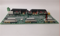
The GE IS200TRPAH2AHE serves as the primary interface between the Mark VIe controller’s safety logic and the turbine’s physical trip mechanisms. It processes high-speed analog data from vibration, speed, and temperature sensors to execute immediate shutdown commands via its robust discrete output drivers.Unlike standard I/O cards, this unit operates within a TMR voting architecture, ensuring that a single card failure does not cause a nuisance trip while maintaining safety integrity. Field records show these cards typically handle over 50,000 operation cycles without contact degradation. The onboard watchdog circuitry monitors internal health every 500 microseconds, forcing a safe state if logic synchronization is lost between the three redundant controllers.
Installation & Configuration Guide
Phase 1: Preparation (10 min)
- CRITICAL: Ensure the turbine is in a safe shutdown state and the Protection Cabinet power is LOCKED OUT.
- Verify the slot location matches the hardware configuration file (
.hwor.io). TRP cards are usually in dedicated protection slots (e.g., Slots 1-3 in a TMR rack). - Inspect the VME pins for any bent leads. Even a slight bend can short the backplane.
- Attach an ESD wrist strap to the cabinet ground stud.
Phase 2: Removal (5–10 min)
- Loosen the two captive retention screws on the card faceplate.
- If equipped with extraction levers, rotate them outward to unseat the card. If not, grip the faceplate firmly and pull straight out.
- Note: Do not touch the exposed components on the card edge.
- Immediately place the removed card into a static-shielding bag. Label it with the slot number and date.
Phase 3: Installation (10 min)
- Unpack the replacement IS200TRPAH2AHE. Verify the revision letter (H2) matches the system requirement.
- Align the card with the upper and lower guide rails. Push gently until the front face is flush with the rack.
- Apply firm, even pressure to seat the 96-pin backplane connector. You should feel a distinct “click” or solid resistance stop.
- Tighten the retention screws securely. Loose screws cause grounding issues and intermittent faults.
Phase 4: Power-On & Test (10 min)
- Restore control power (do not energize field trip solenoids yet).
- Check the LEDs:
- OK LED (Green): Must be steady.
- COMM LED: Should flash indicating VME traffic.
- TRIP LED: Should be OFF (indicating no active trip command).
- Connect to ToolboxST. Navigate to the Diagnostics tab for the TRP pack.
- Perform a “Force Output” test on a non-critical channel (if wired to a test lamp) to verify driver function.
- Verify that the “Voting” status shows “Good” for all three redundant channels.
Troubleshooting Quick Reference
| Symptom | Probability | Action |
|---|---|---|
| Red “Fault” LED Steady | High | Internal self-test failure. Reseat card. If persistent, replace unit. Check for overheating (>70°C). |
| All Outputs De-energized | High | Check 24V DC field supply fuse. Verify “System OK” signal from the main controller (VCMI/PCIM). |
| Voting Mismatch Alarm | Medium | One of the three TRP cards in the TMR set is disagreeing. Swap the suspect card with a known good unit. |
| Intermittent Communication | Medium | Clean backplane contacts. Verify VME terminator plugs are installed at the end of the rack. |
| Output Will Not Reset | Low | Check external wiring for short circuits across the solenoid terminals. Measure output transistor resistance. |

IS200TRPAH2AHE GE
Dimensions, Mounting & Wiring Notes
- Dimensions: 233 mm (H) x 160 mm (D) x 25 mm (W) – Standard 6U VME form factor.
- Mounting: Slides into Mark VIe VME cage. Secured by two front-panel screws.
- Terminal Notes: Uses a heavy-duty removable terminal block (typically 40-50 pins) to handle higher current loads.
- Warning: Trip solenoid wires must be twisted pair and shielded. Connect shields to the cabinet ground bar only.
- Torque: Terminal screws must be torqued to 0.6 Nm. Loose connections cause voltage drop during high-current trip events.
- Wire Gauge: Use 14 AWG minimum for trip output circuits to minimize resistance.
FAQ
Q: Can I mix IS200TRPAH1 and IS200TRPAH2 cards in the same TMR set?
A: No. In a TMR configuration, all three cards must have identical firmware and hardware revisions to ensure synchronized voting. Mixing revisions will cause a “Voting Mismatch” alarm and may inhibit the trip function.Q: What does the “HE” suffix mean in IS200TRPAH2AHE?
A: The suffix indicates the specific hardware revision and component batch. “H2” generally implies an updated design with improved noise immunity compared to earlier “A” or “B” versions. Always cross-reference with the specific turbine control specification sheet.Q: My card passes the self-test but the turbine won’t reset. Why?
A: The card might be healthy, but the logic solver isn’t sending the “Reset” command. Check the controller logic for latched trip conditions. Also, verify the external 24V DC supply voltage is above 21V; low voltage can prevent solenoid energization.Q: Is this card hot-swappable?
A: Technically, the VME bus supports hot-swap, but for Protection cards, it is strictly forbidden to swap them while the turbine is running or in a standby state without bypassing the protection logic first. Doing so could cause an unintended turbine trip.Q: How often should these cards be replaced?
A: GE does not specify a mandatory replacement interval if diagnostics pass. However, many operators proactively replace them after 10-15 years of service due to capacitor aging and thermal cycling fatigue.Q: I smell burning near the terminal block. What do I do?
A: Shut down the system immediately. This indicates a loose terminal connection causing arcing under load, or a shorted solenoid coil. Inspect the terminal block for melted plastic and replace both the card and the terminal block if damage is visible.


