 Tel:
Tel:  Email:
  WhatsApp:
 Description
Key Technical Specifications
| Parameter | Value / Description |
|---|---|
| Channels | 2 independent redundant trip channels (A & B) |
| Input Logic | 24V DC nominal (Trip signal: Loss of Power / De-energize to Trip) |
| Output Relays | High-current form-C contacts rated for solenoid actuation |
| Response Time | < 10 ms from input loss to relay drop-out |
| Diagnostics | Continuous watchdog timer, coil health check, power monitoring |
| Isolation | Galvanic isolation between inputs, outputs, and backplane |
| Operating Temp | -30°C to +65°C |
| Communication | Status feedback to VCMI/VCSC via backplane (non-critical path) |
| Mounting | Standard Mark VIe VME-style rack slot |
| Weight | Approx. 0.9 kg (2.0 lbs) |
| Compliance | SIL-2 capable architecture (system dependent), CE, UL |
| Revision | “C” suffix indicates updated component reliability and noise immunity |
Product Introduction
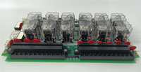
The GE IS200TREGH1BEC is the critical safety heart of the Mark VIe turbine protection system, designed to physically disconnect fuel and stop the turbine in emergency scenarios. Unlike standard I/O cards that rely on software scanning, this board operates on a “de-energize to trip” principle, ensuring that any loss of power, communication, or internal fault automatically triggers a safe shutdown.This “C” revision enhances the reliability of the internal watchdog circuits and improves electromagnetic compatibility (EMC) compared to earlier “A” or “B” versions, making it less susceptible to false trips during electrical grid disturbances. Field engineers value this module for its ability to perform continuous self-checks on the trip solenoid circuits without needing a manual test sequence. (Note: This card is part of a redundant pair in most configurations; never remove both TREG cards simultaneously while the turbine is running.)
Installation & Configuration Guide
Preparation (15 min)
Gather a multimeter, ESD wrist strap, and the specific turbine protection wiring diagram. Critical: Ensure the turbine is in a safe state (stopped or on turning gear) before working on trip circuits. Verify the “Trip Healthy” status on the HMI. Inspect the new IS200TREGH1BEC for bent backplane pins and verify the revision level matches the system requirement.
Removal (5–10 min)
If replacing one card in a redundant pair, ensure the remaining card shows “Healthy.” Disconnect the terminal block (TB-3). Remove the two front-panel retention screws. Slide the card out gently. If resistance occurs, stop immediately—forcing it damages the backplane. Label all trip circuit wires clearly; mixing Channel A and Channel B wires can disable redundancy.
Installation (10 min)
Align the IS200TREGH1BEC with the slot guides. Push firmly but evenly until the backplane connector seats fully. You should feel a distinct solid stop. Reinstall retention screws and reconnect the TB-3 block. Torque terminals to 0.5 Nm. (Over-tightening can crack the terminal block housing, leading to high-resistance connections that cause nuisance trips.)
Power-On & Test (15 min)
Restore 24V DC control power. Observe the “OK” and “Trip Healthy” LEDs; they must turn solid green within 5 seconds. If the “Fault” LED illuminates, check the internal watchdog status via ToolboxST. Perform a partial stroke test or simulated trip test only if the turbine is offline or the procedure allows online testing of one channel. Verify that the trip relay drops out when the input signal is removed.
Troubleshooting Quick Reference
| Symptom | Probability | Action |
|---|---|---|
| “Fault” LED Red | High | Check 24V DC supply voltage. Inspect internal watchdog timer status in diagnostics. |
| Nuisance Trip | Medium | Investigate external wiring for intermittent shorts or ground faults. Check for EMI noise on trip lines. |
| Relay Fails to Reset | Medium | Verify reset signal logic. Check if the trip solenoid circuit has an open fuse or broken wire. |
| Communication Loss | Low | Reseat the card. Check backplane pins. Note: Communication loss usually does not cause a trip on TREG cards (fail-safe design). |
| Channel Mismatch Alarm | Low | Compare status of Channel A and Channel B. If one is faulty, isolate and replace that specific card. |
Dimensions, Mounting & Wiring Notes
- Dimensions: 160 mm (H) × 120 mm (W) × 45 mm (D) approx.
- Mounting: Slides into standard Mark VIe VME-style rack slots. Secured by two front-panel screws.
- Terminal Notes: Uses removable TB-3 terminal block. Wire gauge 14–18 AWG recommended for trip circuits to minimize voltage drop. Shield drains must connect to the chassis ground bar. Keep trip wiring separate from high-voltage AC cables to prevent induced noise.
Quality Transparency Strategy (SOP)
We treat every IS200TREGH1BEC as a life-safety component. Our inspection process begins with strict origin verification, checking lot numbers against GE manufacturing records to rule out counterfeits. We physically inspect the PCB for reflow marks, replaced relays, or signs of thermal stress that suggest previous field failures.Live functional testing occurs on a dedicated Mark VIe simulation rack equipped with dummy load solenoids. We power up the card, run the full self-diagnostic sequence, and simulate various fault conditions (power loss, watchdog timeout, input open) to verify the relay drops out within the specified 10ms window. We measure contact resistance on the output relays to ensure they can handle the inrush current of real trip solenoids.Electrical testing includes insulation resistance checks (>10 MΩ @ 500V) and ground continuity verification. We record the exact firmware version and document revision levels, photographing jumper positions before any adjustment. Final QC involves a signature sign-off, anti-static bagging, and double-boxing with bubble wrap. Function verified under test conditions; always validate in your specific turbine logic before returning to service.
IS200TREGH1BEC GE
Technical Pitfall Guide
Redundancy Mismanagement: The biggest risk is removing both TREG cards (Channel A and B) while the turbine is running. This will cause an immediate unit trip. Always verify which channel you are pulling and confirm the other channel is “Healthy” and carrying the load. Label your tools and cards clearly to avoid mixing them up.Wiring Polarity & Logic: The TREG system typically works on a “de-energize to trip” basis. If you wire a device that expects “energize to trip” without adjusting the logic or interface relays, the turbine may trip immediately upon power-up or fail to trip during an emergency. Double-check the wiring diagram against the physical terminal labels.Ground Loops on Trip Lines: Noise induced on the trip wiring can cause the internal diagnostics to flag a fault, potentially leading to a nuisance trip. Ensure shield grounds are connected at the cabinet end only. Do not ground the shield at the solenoid end if it creates a loop between different ground potentials.ESD Damage to Watchdog Circuit: The internal watchdog timer is sensitive. Technicians have damaged the timing circuitry by touching the backplane pins without an ESD strap. This damage might not show up immediately but can cause the card to fail a self-test days later. Wear the strap. Ground yourself.Ignoring Diagnostic Alarms: Sometimes a “Minor Fault” alarm appears on the HMI for the TREG card. Operators often ignore these if the turbine is running. However, this could indicate a degraded relay coil or a failing power supply component that will result in a failure-to-trip during a real emergency. Investigate all TREG alarms immediately during the next opportunity.
FAQ
Q: Can I operate the turbine with only one TREG card installed?
A: Yes, the system can run on a single channel (non-redundant mode), but it is not recommended for extended periods. The system will likely generate a “Redundancy Lost” alarm. Return to dual-channel operation as soon as possible to maintain safety integrity.Q: What does it mean if the “Trip Healthy” LED is off but the “OK” LED is on?
A: This usually indicates that the external trip circuit (solenoids/wiring) has an open loop or the input signal from the protection logic is missing. The card itself is functional, but the path to trip is broken. Check the external wiring and fuses.Q: Is the IS200TREGH1BEC compatible with Mark V systems?
A: No. This board uses the Mark VIe backplane architecture and communication protocol. It will not physically fit or communicate with Mark V racks. Mark V systems use different trip modules (e.g., TMR trip boards).Q: How often should I perform a trip test on this card?
A: Follow your plant’s maintenance schedule, typically every 6–12 months. Many modern systems allow for online partial stroke testing of one channel while the other maintains protection. Never test both channels simultaneously while the turbine is synchronized to the grid.Q: Do you provide a warranty on refurbished TREG cards?
A: Yes, all tested surplus units come with a 12-month warranty covering functional failures. Given the safety-critical nature of this component, we recommend purchasing from suppliers who provide full functional test reports.Q: What if the card fails the self-test upon arrival?
A: Contact us immediately. We will issue a replacement or refund. Do not attempt to repair the internal relay or watchdog circuitry yourself, as this voids the warranty and compromises the safety certification of the device.