 Tel:
Tel:  Email:
  WhatsApp:
 Description
Key Technical Specifications
| Parameter | Specification |
|---|---|
| Bus Interface | VME64x (32-bit) |
| Application | Turbine Emergency Trip (ETS) |
| Architecture | TMR (Triple Modular Redundant) Ready |
| Output Type | Discrete (Solenoid Driver) |
| Output Voltage | 24V DC Nominal (Range: 18-32V DC) |
| Max Output Current | 2.5 A continuous per channel |
| Peak Current | 5.0 A (for 100ms inrush) |
| Channels | 8 Independent Outputs |
| Response Time | < 2 ms (Logic to Output Change) |
| Isolation | 1500 VAC (Channel to Logic/Bus) |
| Operating Temp | -30°C to +70°C |
| Power Requirement | +5 VDC (Logic), +24 VDC (Field Power) |
| Connector | 96-pin DIN 41612 + Heavy-Duty Terminal Block |
| Dimensions | 233 mm x 160 mm (6U VME) |
| Weight | 0.50 kg |
Product Introduction
The GE IS200TPROH1BCB acts as the final execution element in the Mark VIe safety chain, converting digital voting logic into physical power to energize or de-energize turbine trip solenoids. It is engineered to handle the high inrush currents required by industrial solenoids while maintaining electrical isolation from the sensitive VME backplane.This unit operates strictly within a TMR voting scheme, meaning it requires agreement from at least two of three redundant controllers to change state, preventing nuisance trips from single-point failures. Field data indicates these drivers can sustain over 100,000 switching cycles without contact welding or transistor degradation. The onboard diagnostics continuously monitor output load integrity, detecting open circuits or shorted solenoids within one logic scan (typically <10 ms).
Installation & Configuration Guide
Phase 1: Preparation (10 min)
- CRITICAL: Place the turbine control system in “Maintenance Mode” or bypass the protection logic before touching any TPR cards.
- Verify the target slot matches the hardware configuration file (
.hw). TPR cards are typically located in the first three slots of the protection rack for TMR synchronization. - Inspect the 96-pin VME connector for bent pins. A single bent pin can short the 24V field power to the 5V logic bus, destroying the entire rack.
- Attach an ESD wrist strap to the unpainted metal of the cabinet chassis.
Phase 2: Removal (5–10 min)
- Loosen the two captive retention screws on the faceplate completely.
- Engage the extraction levers (if present) or grip the faceplate edges firmly. Pull straight out with steady pressure.
- Warning: Do not wiggle the card side-to-side. This damages the backplane receptacles.
- Immediately place the removed card into an anti-static bag. Tag it with the slot number and removal date.
Phase 3: Installation (10 min)
- Unpack the replacement IS200TPROH1BCB. Verify the revision “H1” and suffix “BCB” match the system bill of materials.
- Align the card guides with the rack rails. Ensure the top and bottom guides are fully engaged before pushing.
- Push the card inward until the backplane connector seats fully. You will feel a firm mechanical stop.
- Tighten the retention screws to spec (0.5 Nm). Loose screws compromise the shield grounding and can cause EMI issues.
Phase 4: Power-On & Test (10 min)
- Restore control power only (keep field solenoid power off initially if possible for safety check).
- Observe LEDs:
- OK (Green): Must be solid. Flashing indicates boot or self-test failure.
- COMM: Should flash rapidly, indicating VME traffic.
- OUTPUT Status: Verify LEDs match the expected safe state (usually de-energized for trip outputs in a safe state).
- Connect via ToolboxST. Go to the Diagnostics view for the TPR pack.
- Check for “Open Load” or “Short Circuit” alarms.
- Perform a supervised output test: Force one output ON briefly while monitoring the connected test lamp or multimeter. Verify voltage rise time.
- Confirm “Voting Good” status in the TMR configuration menu.
Troubleshooting Quick Reference
| Symptom | Probability | Action |
|---|---|---|
| Red Fault LED Solid | High | Internal hardware failure or watchdog timeout. Reseat card. If fault persists, replace unit immediately. |
| “Voting Mismatch” Alarm | High | One card in the TMR trio is disagreeing. Swap the suspect card with a spare. Check firmware versions on all three. |
| Output Won’t Energize | Medium | Check external 24V DC fuse/breaker. Measure voltage at the terminal block. Verify logic “Permissive” signals are active. |
| Intermittent Comm Loss | Medium | Clean backplane contacts with approved contact cleaner. Ensure VME terminators are present at the rack ends. |
| “Open Load” Alarm | Low | Check wiring continuity to the solenoid. Measure solenoid coil resistance (should be 10-50 Ω typically). |
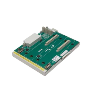
IS200TPROH1BCB GE
Dimensions, Mounting & Wiring Notes
- Dimensions: 233 mm (H) x 160 mm (D) x 25 mm (W) – Standard 6U VME form factor.
- Mounting: Slides into standard Mark VIe VME cage. Secured by two front-panel screws.
- Terminal Notes: Uses a heavy-duty, high-current removable terminal block.
- Warning: Trip solenoid wiring must be twisted pair and shielded. Ground shields at the cabinet entry point only to avoid ground loops.
- Torque: Terminal screws must be torqued to 0.6–0.8 Nm. Loose connections cause voltage drop during the high-current inrush of solenoid activation.
- Wire Gauge: Use 14 AWG (2.5 mm²) minimum for all trip output circuits. Do not use daisy-chained wiring; run home-runs to the terminal block.
FAQ
Q: Can I use an IS200TPROH1BCB to replace an older IS200TPROH1ACA?
A: Generally yes, as they share the same functional role, but you must verify the firmware compatibility matrix in ToolboxST. The “BCB” revision may have updated component tolerances that require a specific firmware patch to operate correctly in a mixed-revision TMR set.Q: Why does the card throw a “Short Circuit” alarm when the solenoid is connected?
A: This often happens if the solenoid coil resistance is lower than the card’s detection threshold (typically <5 Ω). Alternatively, check for moisture or debris in the terminal block causing a partial short between pins.Q: Is this card hot-swappable?
A: While the VME bus supports hot-swap, swapping a Protection output card on a running turbine is extremely risky. It can cause a momentary loss of voting redundancy or an unintended trip. Always follow the plant’s specific “Online Card Replacement” procedure and bypass logic if available.Q: What does the “BCB” suffix signify?
A: It denotes the specific hardware revision and component supplier batch. “B” usually indicates a second revision of the base board, and “CB” refers to specific component changes. Functionally, it should behave identically to other “H1” revisions provided the firmware matches.Q: My card works in the test bench but fails in the rack. Why?
A: Check the backplane slot voltage. A weak +5V or +24V supply at that specific slot can cause boot failures. Also, verify the slot configuration in the .hw file matches the physical location of the card.Q: How do I know if the TMR voting is working correctly?
A: In ToolboxST, navigate to the TMR diagnostic page. You should see three green checkmarks indicating all three controllers (R, S, T) are agreeing on the output state. Any yellow or red indicator signifies a voting mismatch that needs immediate investigation.