 Tel:
Tel:  Email:
  WhatsApp:
 Description
Key Technical Specifications
| Parameter | Value / Description |
|---|---|
| Input Channels | 24 independent discrete inputs |
| Voltage Rating | 24V DC nominal (Operating range: 18–30V DC) |
| Input Type | Supports both dry contacts and wet voltage sources |
| Logic Threshold | “On” > 15V DC; “Off” < 5V DC (typical) |
| Input Impedance | Approx. 3.3 kΩ per channel |
| Isolation | Channel-to-channel and channel-to-ground isolation (500V) |
| Scan Rate | Configurable, typically 10–20 ms per scan |
| Current Draw | Approx. 7 mA per active channel @ 24V |
| Operating Temp | -30°C to +65°C |
| Communication | Backplane interface to VCMI/VCSC controllers |
| Diagnostics | Per-channel LED status indicators, open/short detection |
| Compliance | CE, UL listed components (system dependent) |
Product Introduction
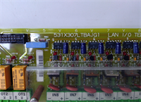
The GE IS200TDBTH6ABC is a high-density discrete input module designed for the Mark VIe control platform, used extensively to monitor the status of limit switches, pressure switches, valve position indicators, and auxiliary relay contacts. The “H” designation indicates it belongs to the high-reliability series, while the “C” revision often includes updated component sourcing and improved noise immunity compared to earlier “A” or “B” versions.Plant operators rely on this board for critical interlocks and permissive logic. Its robust isolation prevents ground loops from affecting the controller when field wiring runs long distances through electrically noisy environments like turbine halls. (Note: Ensure your system firmware supports the specific diagnostic features of the “H” series before enabling advanced fault reporting.)
Installation & Configuration Guide
Preparation (10 min)
Collect a multimeter, ESD wrist strap, and the latest I/O configuration file. Shut down the Mark VIe chassis power if possible; if performing online replacement, verify the redundancy status. Inspect the new IS200TDBTH6ABC for bent backplane pins. Ensure you have the correct TB-3 terminal block ready for wiring.
Removal (5–10 min)
Unplug the terminal block from the existing card. Remove the two front-panel mounting screws. Slide the faulty card out gently. If it sticks, check for obstructions—do not force it. Label wires if the terminal block lacks clear markings, especially for critical trip or permissive signals.
Installation (10 min)
Align the new board with the rack guides. Push evenly until the backplane connector seats fully. You should feel a firm stop. Secure with the two front screws. Reattach the terminal block, ensuring wire strands are not pinched. Torque terminals to 0.5 Nm. (Over-torquing cracks the terminal housing, leading to intermittent signal loss.)
Power-On & Test (10 min)
Apply 24V DC control power. Watch the “OK” LED; it should turn solid green within 5 seconds. If it flashes, verify the DIP switch settings (if applicable) match the system configuration. Use a 24V DC source to simulate a “closed” contact on one channel; verify the status change in the ToolboxST software. Check for any “Channel Fault” LEDs.
Troubleshooting Quick Reference
| Symptom | Probability | Action |
|---|---|---|
| “OK” LED Flashing Red | High | Check 24V DC supply. Verify firmware compatibility with main controller. |
| All Channels Read Zero | Medium | Confirm common return wiring is intact. Check for blown fuse on the board (if equipped). |
| Single Channel Stuck On/Off | Medium | Inspect field device and wiring for shorts or opens. Measure voltage at the terminal block. |
| Intermittent Signal Noise | Low | Check shield grounding. Ensure shield is grounded at one end only. Verify no AC induction on DC lines. |
| High Temperature Alarm | Low | Check cabinet cooling fans. Ensure airflow around the card is not blocked. |
Dimensions, Mounting & Wiring Notes
- Dimensions: 160 mm (H) × 120 mm (W) × 45 mm (D) approx.
- Mounting: Slides into standard Mark VIe VME-style rack slots. Secured by two front-panel screws.
- Terminal Notes: Uses removable TB-3 terminal block. Wire gauge 14–18 AWG recommended. Shield drains must connect to the chassis ground bar. For dry contacts, ensure the external 24V source polarity matches the card’s common connection scheme.
Quality Transparency Strategy (SOP)
Every IS200TDBTH6ABC undergoes strict incoming inspection. We verify origin by checking lot numbers against GE databases to eliminate counterfeit risks. Physical inspection looks for reflow marks, replaced components, or corrosion that suggests field abuse. Accessories like terminal blocks are verified for authenticity.Live functional testing happens on a dedicated Mark VIe test rack. We power up the card, execute a self-test, and establish a communication handshake with a VCMI controller. We simulate “On” and “Off” states on all 24 channels to verify response time and logic thresholds. A 24-hour load test runs to identify thermal drift or intermittent connections.Electrical testing includes insulation resistance checks (>10 MΩ @ 500V) and ground continuity verification. We record the exact firmware version and document revision levels, photographing DIP switch and jumper positions before any adjustment. Final QC involves a signature sign-off, anti-static bagging, and double-boxing with bubble wrap. Function verified under test conditions; always validate in your specific turbine logic.
IS200TDBTH6ABC GE
Technical Pitfall Guide
Firmware Mismatch: The Mark VIe system requires strict firmware alignment between I/O boards and the main controller. Installing an IS200TDBTH6ABC with older firmware than the VCSC controller can cause “Config Mismatch” faults or disable specific diagnostic features. Example: A facility faced a delay because the spare card had Rev A firmware while the system ran Rev D. Always check the toolpack version before installation.Common Return Wiring Errors: Unlike some analog cards, discrete inputs often share common returns within groups. If you wire a 24V source to the wrong common terminal, you can short out the power supply or damage the input circuitry. Always trace the common return path in the wiring diagram before energizing.Wet vs. Dry Contact Confusion: This card supports both, but the wiring differs. For dry contacts, you must provide an external 24V source. For wet contacts, the field device provides the voltage. Mixing these up (e.g., applying 24V to a dry contact input that already has internal pull-ups configured incorrectly) can lead to false readings or damage.ESD Damage Risk: The input optocouplers are sensitive to electrostatic discharge. Technicians have damaged input channels by touching connector pins without an ESD strap. The damage might not be immediate; sometimes it appears as increased susceptibility to noise after weeks of operation. Wear the strap. Ground yourself.Ground Loop Issues: Improper shielding causes significant noise on discrete signals, leading to chatter (rapid on/off cycling). Connecting shields at both the field device and the cabinet end creates a ground loop. Always ground the shield at the cabinet end only. Isolate the field end.
FAQ
Q: Can I mix 24V DC and 125V DC inputs on this same board?
A: No. The IS200TDBTH6ABC is rated for 24V DC nominal inputs only. Applying 125V DC will likely destroy the input circuitry immediately. For 125V DC signals, you need a different model (e.g., IS200TDIGH1A or similar high-voltage discrete board).Q: My “OK” LED is green, but I see no data in the HMI. What’s wrong?
A: Likely a configuration mismatch or communication timeout. Check if the controller recognizes the card in the hardware config tree. Sometimes a simple reboot of the controller clears the handshake error.Q: Do you provide a calibration certificate with refurbished units?
A: We provide a functional test report showing pass/fail status for all channels. Discrete cards do not typically require “calibration” in the analog sense, but we verify logic thresholds. NIST-traceable reports are available as a paid add-on if required by your QA team.Q: Is this card compatible with the Mark V system?
A: No. This board uses the Mark VIe backplane architecture and communication protocol. It will not physically fit or communicate with Mark V racks. You need a complete system upgrade to use this hardware.Q: How quickly can you ship a replacement?
A: Most orders ship within 24 hours if marked “In Stock.” Custom testing requests may add 2–3 days. We keep a rotating inventory of common Mark VIe cards to support urgent outages.Q: What happens if I plug in a 120V AC source into an input channel by mistake?
A: The board has some protection, but 120V AC exceeds the rating significantly and will likely blow the internal fuse or damage the input optocoupler/resistor network. Always double-check your wiring before applying power. If it happens, test the channel with a 24V source before putting it back in service.