 Tel:
Tel:  Email:
  WhatsApp:
 Description
Key Technical Specifications
| Parameter | Specification |
|---|---|
| Channel Count | 16 Configurable Discrete Channels (TMR) |
| Logic Level | 24V DC Nominal (18–32V Range) |
| Redundancy | Triple Modular Redundant (TMR) Architecture |
| Input Impedance | > 10 kΩ (when configured as Input) |
| Output Current | 0.5A per channel (max), 4A total board limit |
| Response Time | < 10ms (Input scan), < 15ms (Output update) |
| Isolation | 500V AC (Channel to Ground/Backplane) |
| Operating Temp | -30°C to +65°C |
| Power Supply | 24V DC (via backplane, redundant feeds) |
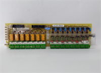
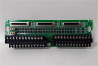
| Connector Type | Pluggable Euro-style terminal block |
| Diagnostic Features | Open wire detection (Input), Short circuit protection (Output), TMR mismatch detection |
| LED Indicators | Per-channel status + Board Fault + TMR Sync Status |
| Compliance | SIL-2 Capable (in TMR configuration), CE, UL |
Product Introduction
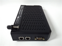
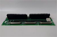
The IS200TBCIS2CCD is a high-integrity discrete I/O board designed specifically for the GE Mark VIe TMR (Triple Modular Redundant) control system. It handles binary signals for critical auxiliary systems such as emergency shutdown valves, fire protection solenoids, pump status feedback, and alarm indications.This “D” revision incorporates enhanced short-circuit protection on output channels and improved noise immunity on inputs compared to earlier “A”, “B”, or “C” versions. The board’s defining feature is its flexibility: each of the 16 channels can be software-defined as either an input or an output, allowing for optimized system design without hardware changes (in most cases). In a TMR setup, three independent processors vote on the state of these I/O points; the IS200TBCIS2CCD ensures that a single point failure in one channel does not compromise the safety logic or cause a false trip. Field data confirms exceptional reliability in harsh power plant environments with high electrical transient levels.
Installation & Configuration Guide
Phase 1: Preparation (10 min)
Identify the correct slot in the Mark VIe TMR rack (usually grouped with other TMR I/O packs). Perform Lock Out/Tag Out (LOTO) on the control cabinet power. Verify zero voltage at the bus terminals. Attach an ESD wrist strap. Gather a small flathead screwdriver, torque wrench, and multimeter. Crucial: Check the system configuration file (.cfg) to confirm which channels are defined as Inputs and which as Outputs. While many “D” revisions are software-configurable, verify if your specific unit requires physical jumper settings to match the logic definition.
Phase 2: Removal (5–10 min)
Disconnect all field wiring from the pluggable terminal block first. Do not pull wires directly from the board terminals. Release the top and bottom ejector levers. Slide the board out smoothly along the guide rails. If you feel resistance, stop immediately—forcing it bends the delicate backplane pins essential for TMR synchronization. Place the removed board in an anti-static bag. Label the terminal block wires clearly if the block is being reused or transferred to the new board.
Phase 3: Installation (10 min)
Inspect the new IS200TBCIS2CCD backplane connector for any bent pins under a bright light. Verify any required hardware jumpers are set to match your configuration (Input vs. Output mode) if applicable. Align the board with the guide rails and slide it in until fully seated; listen for the distinct click of the connector mating. Lock the ejector levers firmly. Reattach the terminal block, tightening screws to 0.5 Nm torque. Ensure no bare wire is exposed. Double-check wiring polarity for output channels driving active loads.
Phase 4: Power-On & Test (10 min)
Restore power to the rack. Observe the status LEDs; solid green lights on all three redundant controllers indicate successful initialization and TMR synchronization. A flashing red light indicates a voting mismatch, configuration error, or hardware fault. Use the engineering workstation to force output states and verify external devices (lights, relays) respond correctly across all three legs. Simulate input signals (apply 24V DC) to verify the HMI reflects the correct status and that no “TMR Mismatch” alarms occur. Check for any “Short Circuit” or “Open Wire” diagnostic alarms on specific channels.
Troubleshooting Quick Reference
| Symptom | Probability | Action |
|---|---|---|
| All channels inactive | High | Check 24V DC backplane supply fuses. Verify power distribution board health. |
| TMR Mismatch Alarm | Medium | One controller sees a different state than the others. Check field wiring for intermittent connections. Reseat the board. Check configuration file consistency. |
| Output channel fails to energize | Medium | Check for short circuit in field wiring. Verify load current does not exceed 0.5A. Confirm channel is configured as Output in .cfg. |
| Input channel reads incorrect state | Medium | Verify field voltage level (must be >18V DC for “High”). Check for ground loops or floating grounds interfering with the signal. |
| “Short Circuit” Alarm | Medium | Disconnect field wiring and measure resistance. Look for pinched cables or failed solenoids. |
| LED Flashing Red | Low | Firmware mismatch or board defect. Reseat board; if persistent, replace unit. Verify .cfg file matches hardware revision. |
IS200TBCIS2CCD GE
Dimensions, Mounting & Wiring Notes
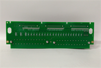
- Dimensions: Approx. 160mm (H) x 120mm (W) x 45mm (D).
- Mounting: Standard Mark VIe backplane slot. Secured by integrated locking levers.
- Terminal Notes: Accepts 14–22 AWG stranded wire. Strip length: 7mm max. Use ferrules for fine-strand wire to prevent fraying and ensure good contact.
- Warning: Do not exceed the total board current limit (4A) even if individual channels are within spec. Distribute high-current loads across multiple boards if necessary. Keep discrete output cables separate from sensitive analog signal lines to prevent noise coupling. Never apply AC voltage or voltages >32V DC to this board.
FAQ
Q: Is the IS200TBCIS2CCD compatible with Mark V systems?
A: No. This board uses the Mark VIe proprietary backplane and TMR communication protocol. It will not physically fit or function in a Mark V rack.Q: Can I change a channel from Input to Output just by changing the software?
A: Generally yes for the “D” revision, as it often features auto-sensing or software-switchable drivers. However, always consult the specific hardware manual for your serial number range, as some early “D” units might still require a physical jumper change to enable the output driver circuitry.Q: How quickly can you ship a replacement?
A: Tested units are in stock and ship same-day if ordered before 2 PM EST. International delivery usually takes 3–5 days via express courier.Q: What happens if I connect 120V AC to this board?
A: Catastrophic failure. This board is strictly 24V DC. Connecting higher voltages or AC will instantly destroy the input/output drivers and likely damage the backplane and adjacent cards. Always verify voltage levels with a multimeter before connecting.Q: Does the package include the terminal block?
A: Yes, unless the listing explicitly states “Board Only.” Always verify the product photos to ensure the pluggable terminal block is included. Missing terminals will halt installation.Q: Can this board drive a large contactor directly?
A: No. The maximum current per channel is 0.5A. Use this board to drive an intermediate interposing relay, which then switches the larger contactor coil. Direct driving of large inductive loads will weld the internal contacts or trigger the short-circuit protection immediately.