
 Tel:
Tel:  Email:
  WhatsApp:
 Description
Key Technical Specifications
| Parameter | Specification |
|---|---|
| Bus Interface | VME64x (32-bit) |
| Communication Ports | 4 Independent Channels |
| Protocol Support | Modbus RTU, ASCII, Generic Serial |
| Signal Standards | RS-232, RS-422, RS-485 (Software/Jumper selectable) |
| Max Baud Rate | 115,200 bps (some configs support 230.4 kbps) |
| Data Bits | 7 or 8 bits |
| Stop Bits | 1 or 2 bits |
| Parity | None, Even, Odd |
| Isolation | 500 VAC (Channel to Bus) |
| Operating Temp | -30°C to +70°C |
| Power Requirement | +5 VDC @ 0.8 A (Logic only) |
| Connector Type | 96-pin DIN 41612 (VME) + External Terminal Block |
| Dimensions | 233 mm x 160 mm (6U VME Form Factor) |
| Weight | 0.42 kg |
Product Introduction
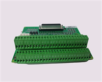
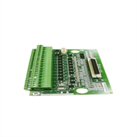
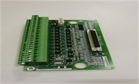
The GE IS200STCIH2A serves as the gateway for serial data integration within the Mark VIe control ecosystem. It enables the turbine controller to poll external instruments—such as emissions monitors, fuel flow meters, or vibration analyzers—and ingest that data directly into the control logic for real-time decision making.This revision (H2) features enhanced UART controllers that reduce data dropout rates during high-traffic bursts, a common issue in older revisions when polling multiple devices simultaneously. Field logs indicate successful operation at maximum baud rates (115.2k) over distances up to 1,200 meters when using RS-485 with proper termination. The card supports both master and slave modes, allowing flexible network topologies without additional hardware converters.
Installation & Configuration Guide
Phase 1: Preparation (10 min)
- Verify rack power is OFF. While serial cards are less sensitive than protection cards, backplane shorts are still a risk.
- Check the I/O configuration file (
.io) to confirm the assigned slot number and port definitions (baud rate, parity). - Inspect the VME pins. Ensure no debris is lodged in the connector housing.
- Safety: Ground yourself with an ESD strap. Static discharge can fry the UART chips instantly.
Phase 2: Removal (5–10 min)
- Disconnect the external serial cable from the terminal block before unscrewing the card. Pulling on the cable while removing the card can damage the terminal pins.
- Loosen the two captive retention screws on the faceplate.
- Use the ejector levers or pull firmly on the faceplate to unseat the card from the backplane.
- Slide the card out and place it in an anti-static bag.
Phase 3: Installation (10 min)
- Remove the IS200STCIH2A from packaging. Verify the “H2” label.
- Align the card with the rack guides. Push straight in until the backplane connector seats fully.
- Tighten the retention screws. Ensure the card face is flush with the rack; gaps indicate improper seating.
- Reconnect the external terminal block. Critical: Verify pinout orientation. Reversing power/data pins can destroy connected field devices.
Phase 4: Power-On & Test (10 min)
- Restore rack power.
- LED Check:
- Green OK LED: Steady on indicates successful boot.
- TX/RX LEDs: Should flash intermittently if traffic is present. If solid off, check cabling or device power.
- Open ToolboxST. Navigate to the “Communications” diagnostic tab.
- Verify “Port Active” status for all configured channels.
- Perform a loopback test on one port (short TX to RX) to verify data transmission integrity. You should see transmitted bytes echoed back immediately.
- Poll the actual field device. Check for “Timeout” errors. If timeouts occur, verify baud rate matching and termination resistors (120Ω for RS-485).
Troubleshooting Quick Reference
| Symptom | Probability | Action |
|---|---|---|
| No Data Received (Garbage) | High | Baud rate mismatch. Verify controller config matches field device exactly. Check for ground loops causing noise. |
| Port Timeout Errors | High | Wiring fault (open circuit) or missing termination resistor on RS-485 bus. Check cable continuity. |
| Red Fault LED | Medium | Internal UART chip failure or firmware corruption. Reseat card. If persistent, replace unit. |
| Intermittent Comm Loss | Medium | Loose terminal block screws. Vibration often loosens these over time. Retorque to 0.5 Nm. |
| Only One Port Works | Low | Configuration error in .io file. Ensure all four ports are explicitly defined and enabled in the hardware map. |
IS200STCIH2A GE
Dimensions, Mounting & Wiring Notes
- Dimensions: 233 mm (H) x 160 mm (D) x 20 mm (W) – Standard 6U VME form factor.
- Mounting: Slides into standard 19-inch rack VME cage. Secured by two front-panel screws.
- Terminal Notes: Uses a removable screw-terminal block (typically 20-30 pins depending on channel breakout).
- Warning: RS-485 networks require a daisy-chain topology. Do not star-wire. Add a 120Ω termination resistor at the furthest end of the line.
- Wire Gauge: Accepts 18 AWG to 24 AWG stranded copper.
- Shielding: Use shielded twisted pair (STP) cable. Connect the shield to the cabinet ground bar at one end only to prevent ground loops.
FAQ
Q: Can I mix RS-232 and RS-485 devices on the same IS200STCIH2A card?
A: Yes, but not on the same physical port. Each of the four channels can be independently configured via jumpers or software (depending on the specific sub-revision) for either protocol. You cannot split a single port to drive both standards simultaneously without external converters.Q: Why am I getting “Frame Errors” in the diagnostic log?
A: This usually indicates a baud rate mismatch or electrical noise on the line. If the baud rates match, check your grounding. A potential difference between the controller ground and the field device ground can corrupt data bits. Isolate the signal using an optical isolator if necessary.Q: Is the IS200STCIH2A backward compatible with Mark V systems?
A: No. The Mark V system used different communication architectures (often dedicated LAN cards or older serial packs). This VME-based card is exclusive to Mark VIe.Q: What is the maximum cable length for RS-485 on this card?
A: Theoretically up to 1,200 meters (4,000 ft) at lower baud rates (<9.6 kbps). At 115.2 kbps, keep cable runs under 100 meters to ensure data integrity without repeaters.Q: I replaced the card, but the new one won’t communicate. Did I miss a step?
A: Likely. Did you download the updated hardware configuration to the controller? The new card might have a different internal ID or require a specific firmware load that hasn’t been pushed to the controller yet. Check the “Firmware Mismatch” alarm in ToolboxST.Q: Can I hot-swap this card while the turbine is running?
A: Technically, yes, the VME bus supports it. However, losing serial communication to critical auxiliaries (like gas detectors) might trigger a process alarm or trip depending on your logic voting. It is safer to perform this swap during a planned outage or when the specific auxiliary system can be temporarily bypassed.


