 Tel:
Tel:  Email:
  WhatsApp:
 Description
Key Technical Specifications
| Parameter | Value / Description |
|---|---|
| Input Channels | 8 independent RTD inputs |
| Sensor Types | Pt100, Pt1000, Ni100, Ni120 (Software configurable) |
| Wiring Config | Primarily 3-wire (compensates for lead resistance); supports 2-wire/4-wire with config |
| Measurement Range | -200°C to +850°C (dependent on sensor type) |
| Accuracy | ±0.1% of reading or ±0.5°C (whichever is greater) |
| Excitation Current | < 1 mA (low current to prevent self-heating errors) |
| Isolation | Channel-to-channel and channel-to-ground isolation (500V) |
| Resolution | 16-bit analog-to-digital conversion |
| Communication | Serial interface to VCMI/VCSC (reduces backplane noise) |
| Update Rate | Typically 250ms per channel (configurable) |
| Diagnostics | Open circuit detection, short circuit detection, range check |
| Operating Temp | -30°C to +65°C |
Product Introduction
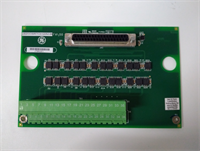
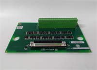
The GE IS200SRTDH2ACB is a specialized temperature acquisition module for the Mark VIe platform, engineered to provide high-accuracy monitoring of critical thermal points in gas and steam turbines. Unlike older parallel bus architectures, the “S” (Serial) designation indicates this board communicates digitized temperature data serially to the main controller, significantly reducing electrical noise susceptibility on the backplane.The “H” series denotes high reliability, and the “B” revision includes updated component tolerances and improved linearization algorithms for non-standard RTD curves. This board is essential for protection logic, such as bearing over-temperature trips or exhaust temperature spread alarms. Its ability to compensate for lead wire resistance in 3-wire configurations ensures accurate readings even with long cable runs from the turbine to the control cabinet. (Note: Always verify the specific RTD curve selected in the ToolboxST software matches the physical sensors installed.)
Installation & Configuration Guide
Preparation (10 min)
Gather a multimeter, ESD wrist strap, and the turbine instrumentation diagram. Power down the Mark VIe chassis if possible; for online replacement, ensure redundancy is active. Inspect the new IS200SRTDH2ACB for bent backplane pins. Verify you have the correct TB-3 terminal block. Check that your RTD sensors are 3-wire types (most common) or note if 2-wire/4-wire adaptation is needed.
Removal (5–10 min)
Disconnect the RTD cables from the terminal block. Remove the two front-panel retention screws. Slide the card out smoothly. If resistance occurs, stop immediately—forcing it damages the backplane pins. Label all RTD leads clearly (e.g., “Bearing 1 A/B/C”) before removal if not pre-tagged. Mixing leads between channels will cause false temperature readings.
Installation (10 min)
Align the IS200SRTDH2ACB with the slot guides. Push firmly but evenly until the backplane connector seats fully. You should feel a distinct “click” or solid stop. Reinstall retention screws and reconnect the sensor cables. Torque terminals to 0.5 Nm. (Over-tightening can crush the wire or damage the terminal block, leading to high-resistance connections and erroneous high-temperature alarms.)
Power-On & Test (15 min)
Restore 24V DC control power. Observe the “OK” LED; it must turn green within 5 seconds. If it flashes red, check firmware compatibility. Use a precision decade resistance box or a calibrated RTD simulator to inject a known resistance (e.g., 138.5 Ω for 100°C on a Pt100). Verify the reading in ToolboxST matches the simulated value within tolerance. Check for “Open Sensor” or “Short Circuit” diagnostics if wires are disconnected intentionally during testing.
Troubleshooting Quick Reference
| Symptom | Probability | Action |
|---|---|---|
| “OK” LED Red | High | Check 24V DC supply. Verify firmware match with main controller. |
| Reading Maxed Out (e.g., 850°C) | High | Indicates an “Open Circuit.” Check for broken wires, loose terminals, or failed sensor element. |
| Reading Minus Scale (e.g., -200°C) | Medium | Indicates a “Short Circuit.” Check for pinched wires or moisture in the junction box. |
| Erratic/Noisy Readings | Medium | Check shield grounding. Ensure shield is grounded at cabinet end only. Verify no VFD interference nearby. |
| Consistent Offset Error | Low | Verify the RTD type (Pt100 vs Pt1000) configured in software matches the physical sensor. Check lead resistance compensation settings. |
Dimensions, Mounting & Wiring Notes
- Dimensions: 160 mm (H) × 120 mm (W) × 45 mm (D) approx.
- Mounting: Slides into standard Mark VIe VME-style rack slots. Secured by two front-panel screws.
- Terminal Notes: Uses removable TB-3 terminal block. Use shielded twisted-pair cable (e.g., Belden 9271 or equivalent) for RTD inputs. Shield drains must connect to the chassis ground bar. Keep RTD cables away from high-current AC conductors to prevent induced noise. For 3-wire sensors, ensure the two legs of the same color are connected to the correct adjacent terminals as per the wiring diagram.
Quality Transparency Strategy (SOP)
We treat every IS200SRTDH2ACB as a critical monitoring component. Our inspection process begins with origin verification, checking lot numbers against GE manufacturing records to rule out counterfeits. We physically inspect the PCB for reflow marks or replaced components that suggest unauthorized repair.Live functional testing occurs on a dedicated Mark VIe simulation rack equipped with high-precision resistance standards. We power up the card, run a self-test sequence, and simulate resistance values across the full range (-200°C to +850°C equivalent) for all 8 channels to verify linearity and accuracy. We specifically test the lead-wire compensation feature by adding artificial resistance to one leg of the 3-wire circuit. A 24-hour load test follows to catch thermal drift issues.Electrical testing includes insulation resistance checks (>10 MΩ @ 500V) and ground continuity verification. We record the exact firmware version and document revision levels, photographing jumper positions before any adjustment. Final QC involves a signature sign-off, anti-static bagging, and double-boxing with bubble wrap. Function verified under test conditions; always validate in your specific turbine logic.
IS200SRTDH2ACB GE
Technical Pitfall Guide
Software/Hardware Mismatch: The most common error is configuring the software for a Pt100 sensor while a Pt1000 is physically installed (or vice versa). This results in massive temperature reading errors (often reading near zero or off-scale). Always cross-reference the sensor nameplate with the ToolboxST configuration before commissioning.Lead Wire Resistance Issues: While the 3-wire configuration compensates for lead resistance, this fails if the resistance of the three wires is not balanced (e.g., one wire is significantly longer or has a bad splice). If the difference in resistance between the legs exceeds the compensation limit, measurement errors occur. Ensure all three wires of an RTD run are the same length and gauge.Ground Loop Noise: RTD signals are low-level resistance measurements. Connecting cable shields at both the sensor head and the cabinet end creates a ground loop, introducing noise that looks like temperature fluctuation. Always ground the shield at the cabinet end only. Isolate the field end.Self-Heating Errors: Although the excitation current is low (<1mA), using the wrong configuration that increases current can cause the RTD element to self-heat, reading higher than the actual process temperature. Do not modify internal jumpers unless explicitly instructed by GE documentation.ESD Damage Risk: The precision analog front-end is sensitive. Technicians have damaged channels by touching the terminal pins without an ESD strap. The damage might manifest as increased noise or drift over time. Wear the strap. Ground yourself.
FAQ
Q: Can I use this board for Thermocouples (TCs)?
A: No. The IS200SRTDH2ACB is designed strictly for RTDs (Resistance Temperature Detectors). For Thermocouples, you must use a TC-specific board (e.g., IS200STCIH1A). Using an RTD board for TCs will result in incorrect readings and potential damage.Q: My temperature reading is stable but consistently 5°C higher than a handheld meter. Why?
A: This could be due to sensor calibration drift, poor thermal contact of the sensor in the well, or a software offset. It could also be lead-wire imbalance if the wires are very long. Compare with another channel reading the same physical point if available, or swap the sensor to isolate the issue.Q: Do you offer a warranty on refurbished units?
A: Yes, all tested surplus units come with a 12-month warranty covering functional failures. We do not cover damage from improper installation, lightning strikes, or power surges.Q: Is this card compatible with the Mark V system?
A: No. This board uses the Mark VIe backplane architecture and serial communication protocol. It will not physically fit or communicate with Mark V racks. Mark V systems use different RTD modules (e.g., TREG/TCQA combinations).Q: How quickly can you ship a replacement?
A: Most orders ship within 24 hours if marked “In Stock.” Custom testing requests may add 2–3 days. We keep a rotating inventory of common Mark VIe cards to support urgent outages.Q: What if the card fails the self-test upon arrival?
A: Contact us immediately. We will issue a replacement or refund. Do not attempt to repair the board yourself as this voids the warranty and calibration integrity.