 Tel:
Tel:  Email:
  WhatsApp:
 Description
Key Technical Specifications
| Parameter | Specification |
|---|---|
| Input Type | Dry Contact or Wet Voltage (Configurable) |
| Channels | 24 Independent Inputs |
| Voltage Rating | 24V DC, 48V DC, or 125V DC (Jumper/User Configurable) |
| Input Current | Approx. 2–5 mA (dependent on voltage setting) |
| Logic Levels | Programmable (Active High/Low) |
| Mounting Type | Mark VIe Backplane Slot |
| Operating Temp | -30°C to +65°C |
| Indicator LEDs | Per-channel status (On = Input Active) |
| Connector Type | 3-tier Euro-style terminal blocks (Removable) |
| Isolation | Optical isolation (Channel groups to backplane) |
| Wire Gauge | 18–12 AWG (Stranded) |
| Weight | Approx. 1.1 kg |
| Compliance | CE, UL, CSA |
Product Introduction
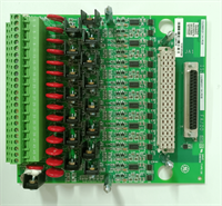
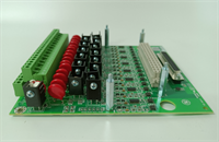
The IS200SDIIH1ADB serves as a versatile interface for discrete field signals within the GE Mark VIe simplex control architecture, accepting both dry contact closures and wet voltage inputs from various plant instruments. It is commonly deployed for monitoring auxiliary pumps, fan statuses, valve limit switches, and pressure safety switches where triple redundancy is not mandated.This board distinguishes itself with flexible voltage configuration, allowing a single card type to serve multiple voltage domains (24V, 48V, 125V) within the same cabinet by adjusting jumpers or dip switches. The “H1” revision typically features robust optical isolators designed to withstand the high electrical noise environment of turbine halls. (Critical: Always verify the voltage rating jumpers match the field supply; applying 125V to a 24V setting will instantly destroy the input circuitry).
Installation & Configuration Guide
Preparation (10 min)
- Execute Lockout/Tagout (LOTO) on the control power feeding the rack.
- Identify the required input voltage (24V, 48V, or 125V) from the site wiring diagram.
- Locate the voltage configuration jumpers on the IS200SDIIH1ADB PCB (usually near the terminal blocks).
- Gather tools: #2 Phillips screwdriver, small flathead (for jumpers), multimeter, ESD strap.
Removal (5–10 min)
- Disconnect all field wiring from the three tiers of terminal blocks. Label every wire clearly (e.g., TB1-1, TB1-2).
- Remove the two mounting screws securing the board to the rack.
- Pull the module straight out from the backplane.
- Real-world detail: Inspect the terminal blocks for signs of arcing or heat discoloration, which indicates a previous over-voltage or loose connection event.
Installation (10 min)
- Configuration Step: Set the voltage jumpers on the new IS200SDIIH1ADB to match the field voltage before installation. Double-check this setting.
- Align the board guides with the rack slots and push firmly until the backplane connector seats.
- Reinstall mounting screws. Torque to 1.5 Nm.
- Reconnect field wiring. Ensure strands are not frayed and ferrules are used if required by site standards.
Power-On & Test (10 min)
- Restore control power to the rack.
- Verify the associated processor card shows no communication faults.
- Activate a field switch or apply voltage to a test channel.
- Observe the corresponding LED on the IS200SDIIH1ADB; it should illuminate immediately.
- Confirm the status change in the Mark VIe Toolbox software or HMI.
Troubleshooting Quick Reference
| Symptom | Probability | Action |
|---|---|---|
| LED On but Software reads 0 | High | Check logic inversion settings in the configuration file. Verify backplane data path. |
| No LED on Active Input | High | Measure voltage at terminals. If 0V, check field fuse or broken wire. If Voltage present, check jumper setting. |
| Flickering LED | Medium | “Chattering” switch or loose wire. Tighten terminal screws. Inspect field device. |
| Burnt Smell/Discoloration | Medium | Immediate Replacement Required. Likely caused by over-voltage (e.g., 125V on 24V setting). |
| Group Failure | Medium | Check common return path or internal fuse for that channel group. |
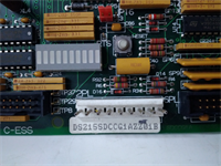
IS200SDIIH1ADB MRP683026 GE
Dimensions, Mounting & Wiring Notes
- Dimensions: Approx. 160mm (H) x 120mm (W) x 90mm (D) — Verify with physical caliper measurement.
- Mounting: Standard Mark VIe backplane slot.
- Terminal Notes: Use stranded wire (18–12 AWG). Ferrules are highly recommended for vibration resistance.
- Clearance: Maintain 75mm clearance in front for wiring access and heat dissipation.
- Warning: NEVER apply AC voltage to this card unless specifically rated (most SDII cards are DC only). Applying AC will destroy the optical isolators.
FAQ
Q: What does the MRP683026 number mean?
A: MRP (Material Requirements Planning) numbers are internal GE manufacturing identifiers. MRP683026 corresponds specifically to the IS200SDIIH1ADB revision, ensuring you receive the correct component update for your system.Q: Can I mix 24V and 125V inputs on the same card?
A: No. The voltage setting on the IS200SDIIH1ADB is global for the entire card (or large groups). You cannot have some channels at 24V and others at 125V on the same board. Use separate cards for different voltage levels.Q: Is this card compatible with TMR systems?
A: Yes, but only for non-critical signals or where external voting is handled by the application logic. For critical protection signals (like Overspeed), a dedicated TMR input card (like TDII) is preferred.Q: How do I change the voltage setting?
A: Locate the jumper block (usually labeled JP1 or similar) on the PCB. Move the shunts to the position marked for your desired voltage (24V, 48V, 125V) as per the silk-screen diagram. Power must be off during this change.Q: Why are there 3 rows of terminals?
A: The three tiers organize the 24 channels efficiently, typically grouping 8 channels per row with dedicated positive, negative, and shield/return connections.Q: Does this come with a calibration certificate?
A: Discrete input cards generally do not require “calibration” in the analog sense. However, refurbished units undergo a functional loop test to verify all 24 channels respond correctly to input stimuli.