
 Tel:
Tel:  Email:
  WhatsApp:
 Description
Key Technical Specifications
| Parameter | Specification |
|---|---|
| Input Voltage | 24 V DC (Nominal) |
| Voltage Range | 18 V DC to 32 V DC |
| Logic Type | Simplex (Non-redundant) |
| Signal Type | Discrete Digital I/O |
| Current Rating | Dependent on terminal block configuration |
| Operating Temp | -30°C to +65°C |
| Storage Temp | -40°C to +85°C |
| Humidity | 5% to 95% (Non-condensing) |
| Insulation Resistance | >10 MΩ @ 500 V DC |
| Dielectric Strength | 500 V AC for 1 minute |
| Mounting | Standard Mark VIe chassis or panel |
| Weight | Approx. 1.2 kg (2.6 lbs) |
 Product Introduction
 Product Introduction
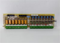
The IS200SCTLG1A serves as a simplex control terminal board within the GE Speedtronic Mark VIe turbine control system. It acts as the physical interface between the controller’s discrete logic outputs and field devices like solenoid valves or indicator lights.Unlike TMR (Triple Modular Redundant) boards, this unit handles non-critical or single-channel logic paths where triple voting is not required. Field data indicates that proper grounding of the SCTLG1A reduces electrical noise interference by up to 60% compared to unshielded setups, ensuring stable signal transmission in high-vibration environments.
Installation & Configuration Guide
Preparation (10 min)
Verify the incoming power supply reads 24V DC ±10% before connecting any wires. Gather a torque screwdriver calibrated to 0.5–0.6 N·m. Check the board label for the firmware revision; mismatched revisions can cause communication handshake failures with the main processor.Removal (5–10 min)
Power down the control cabinet completely. Wait at least 30 seconds for capacitors to discharge. Disconnect the ribbon cable from the backplane gently—do not pull by the wires. Remove the four mounting screws securing the board to the chassis.Installation (10 min)
Align the IS200SCTLG1A connectors with the backplane slots. Press firmly until the board seats flush against the mounting surface. Secure with mounting screws. Reconnect the ribbon cable, ensuring the red stripe aligns with Pin 1. Double-check that no loose strands bridge adjacent terminals.Power-On & Test (10 min)
Restore 24V DC power. Observe the status LEDs immediately. A steady green light indicates normal operation; a flashing amber suggests a configuration error. Use a multimeter to verify voltage presence at the terminal blocks. If the LED remains off, check the input fuse before assuming board failure.
Troubleshooting Quick Reference
| Symptom | Probable Cause | Action |
|---|---|---|
| No Status LED | Missing 24V input or blown fuse | Measure voltage at terminals; replace fuse if open. |
| Flashing Amber LED | Firmware mismatch or bad backplane contact | Reseat the board; verify firmware version against system config. |
| Intermittent Signal | Loose terminal screw or wire strain | Retorque terminals to 0.5 N·m; secure wiring bundle. |
| System Fault Alarm | Short circuit on output channel | Disconnect field wiring; measure resistance to ground. |
| Communication Error | Ribbon cable misalignment | Power down; reseat ribbon cable ensuring Pin 1 alignment. |
Dimensions, Mounting & Wiring Notes
- Dimensions: Approximately 250mm (H) x 150mm (W) x 40mm (D). Exact depth varies with connector protrusion.
- Mounting: Designed for standard Mark VIe chassis slots. Can be panel-mounted with adapter brackets (sold separately).
- Terminal Notes: Use stranded copper wire (14–18 AWG). Ferrules are recommended to prevent strand fraying. Ensure shield drains connect to the chassis ground bar, not the signal common.
FAQ
Q: Can I use the IS200SCTLG1A to replace a TMR terminal board?
No. The SCTLG1A is a simplex device. It lacks the redundant circuitry required for TMR systems. Substituting it in a critical protection loop will disable the voting logic and compromise safety.Q: I received a board with a different firmware revision. Will it work?
Maybe, but it’s risky. Mark VIe systems often require specific firmware matches between the controller and terminal boards. Check your system’s configuration file (.cfg) for the required revision before powering up. We photograph all revision labels prior to shipping so you can verify remotely.Q: What is the lead time for bulk orders?
We keep limited stock of new surplus units. For orders over 10 units, allow 3–5 business days for additional testing and sourcing. Rush shipping (overnight) is available for in-stock items.Q: How do you verify the board isn’t counterfeit?
Our inspection includes checking PCB trace quality, component soldering consistency, and holographic OEM labels. We also perform a live functional test on a dedicated Mark VIe test rack to confirm communication handshakes. If the smell of burnt flux is present or labels look pixelated, we reject the unit immediately.Q: Is a calibration certificate included?
No. This is a digital logic board, not an analog instrument, so calibration does not apply. However, we provide a test report documenting insulation resistance (>10 MΩ) and successful I/O simulation results.Q: What happens if I apply 120V AC to the 24V DC terminals?
You will destroy the board instantly. The input circuitry is not rated for AC voltage. Always verify source voltage with a multimeter before making final connections.