
 Tel:
Tel:  Email:
  WhatsApp:
 Description
Key Technical Specifications
| Parameter | Specification |
|---|---|
| Bus Interface | Internal Ribbon Cable to VME Packs (No direct VME bus) |
| Application | Analog Signal Routing & Conditioning |
| Architecture | Simplex (can be part of TMR system via triple boards) |
| Channel Capacity | Configurable (Typically 32 inputs/outputs per board) |
| Signal Type | ±10 VDC, 4-20 mA (Pass-through) |
| Switching Speed | < 10 µs per channel |
| Isolation | Signal-to-Signal isolation via external terminal boards |
| Operating Temp | -30°C to +70°C |
| Power Requirement | Derived from connected VME packs via ribbon cable |
| Connector Type | High-density ribbon cable connectors (IDC) |
| Dimensions | Approx. 180 mm x 140 mm (Mounts inside I/O cage) |
| Weight | 0.35 kg |
Product Introduction
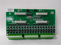
The GE IS200SAMBH1ABA acts as the central nervous system for analog signal management in specific Mark VIe I/O cages. Unlike standard VME cards that plug directly into the backplane, the SAMB board mounts horizontally or vertically within the cage and connects via ribbon cables to the front of the analog input/output VME packs (such as VAIC, VAIX, VROC).Its primary role is to aggregate signals from the field terminal boards (like TBAI) and distribute them to the correct processing cards. In TMR (Triple Modular Redundant) configurations, three SAMB boards are often used to split a single field signal into three identical paths for the R, S, and T controllers, ensuring redundancy. The H1 revision features improved trace layout to minimize crosstalk between high-speed analog channels, a common issue in earlier generations. Field data shows these boards have an extremely low failure rate, with most issues stemming from connector corrosion rather than component failure.
Installation & Configuration Guide
Phase 1: Preparation (10 min)
- CRITICAL: Lock out power to the entire I/O cage. Working on ribbon cables while powered can cause short circuits across multiple channels.
- Identify the specific cage location (e.g., I/O Cage 1, Slot A).
- Verify the replacement board matches the revision “H1” and suffix “ABA”.
- Inspect the ribbon cable connectors on both the board and the mating VME packs for bent pins or debris.
Phase 2: Removal (10–15 min)
- Careful: Disconnect the ribbon cables first. Pull the connectors straight out by the plastic housing, never by the wires.
- Remove any mounting screws or brackets securing the SAMB board to the cage chassis.
- Gently lift the board out. Note the orientation; these boards are often keyed to fit only one way.
- Place the removed board in an anti-static bag.
Phase 3: Installation (10 min)
- Position the new IS200SAMBH1ABA in the mounting slots. Ensure it sits flat and parallel to the other components.
- Secure the board with the mounting screws. Do not overtighten, as this can warp the PCB.
- Reconnect the ribbon cables.
- Critical Check: Ensure Pin 1 (usually marked with a red stripe on the cable) aligns with Pin 1 on the connector. Reversing the cable will send voltage to the wrong pins and can destroy connected VME packs.
- Push connectors firmly until they click or seat fully.
Phase 4: Power-On & Test (10 min)
- Restore power to the cage.
- Observe the LEDs on the connected VME packs (VAIC/VAIX). They should boot normally. If a pack shows a “Hardware Fault,” immediately power down and check the ribbon cable orientation.
- Launch ToolboxST.
- Navigate to the Diagnostics view. Check for “Signal Loss” or “Out of Range” alarms on the channels routed through this SAMB.
- Verification: Inject a known test signal (e.g., 10 mA) at the terminal board. Verify the value appears correctly in the controller logic. If the value is zero or erratic, check the continuity of the ribbon cable path.
Troubleshooting Quick Reference
| Symptom | Probability | Action |
|---|---|---|
| Multiple Channels Dead | High | Ribbon cable disconnected or reversed. Check Pin 1 alignment. Inspect cable for damage. |
| Noisy/Erratic Readings | Medium | Poor ground connection on the SAMB mounting bracket. Clean contact points and retighten screws. |
| Single Channel Failure | Low | Issue likely lies with the specific trace on the board or the mating VME pack channel. Swap VME packs to isolate. |
| VME Pack Won’t Boot | High | Short circuit on the SAMB board pulling down power. Disconnect ribbon cables one by one to identify the faulty path. |
| Intermittent Signal Loss | Medium | Loose ribbon cable connector. Reseat all cables. Check for vibration-induced loosening. |
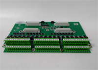
IS200SAMBH1ABA GE
Dimensions, Mounting & Wiring Notes
- Dimensions: Approx. 180 mm x 140 mm (Varies slightly by specific cage mount).
- Mounting: Typically mounts on standoffs or rails inside the I/O cage, perpendicular to the VME backplane.
- Wiring Notes:
- Ribbon Cables: Use only GE-specified shielded ribbon cables. Standard unshielded cables can introduce significant noise into analog signals.
- Bend Radius: Do not bend ribbon cables sharper than 90 degrees near the connector; this can break internal conductors.
- Strain Relief: Ensure cables are tied off or clamped so that vibration does not pull on the connectors.
FAQ
Q: Can I use an IS200SAMBH1ABA in a TMR system?
A: Yes. In a TMR configuration, you typically install three of these boards (one for each redundant leg: R, S, and T). They work in parallel to split the field signals. Ensure all three boards have matching revision levels to avoid signal skew.Q: What is the difference between SAMB and TAMB?
A: SAMB stands for Simplex Analog Multiplexer Board, used primarily in simplex or specific non-redundant paths. TAMB stands for Triple Analog Multiplexer Board, which is specifically designed with internal tracing to facilitate TMR splitting more efficiently. However, in many Mark VIe architectures, multiple SAMB boards are used to achieve the same TMR result. Check your specific system schematic.Q: My ribbon cable looks damaged. Can I replace just the cable?
A: Yes, the ribbon cables are separate part numbers. However, ensure you buy the exact length and pin-count specified for your cage layout. Using a longer cable than necessary can increase capacitance and degrade signal quality.Q: Why are my analog readings drifting after replacing this board?
A: This could be due to a poor ground connection between the SAMB board and the cage chassis. The board relies on the chassis for shielding. Clean the mounting surface and ensure the screws are tight. Also, verify that the ribbon cable shields are grounded at the termination point.Q: Is this board hot-swappable?
A: No. Because the SAMB board distributes power and signals to multiple VME packs via ribbon cables, removing it while powered will interrupt signals to all connected packs, likely causing a turbine trip or process upset. Always perform a controlled shutdown before replacing.Q: Does the “ABA” suffix affect compatibility?
A: The suffix generally refers to the manufacturing batch and minor component updates. Functionally, an “ABA” should replace an “AAA” or “AAB” without issue, but it is best practice to verify the firmware compatibility matrix in ToolboxST to ensure no specific calibration constants are required for the new revision.


