 Tel:
Tel:  Email:
  WhatsApp:
 Description
Key Technical Specifications
- Input Voltage: 24V DC nominal (Range: 18–32V DC)
- Logic Type: Positive/Negative logic selectable via software configuration
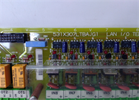
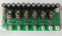
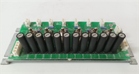
- Channel Count: 16 discrete input channels per board
- Redundancy Architecture: Supports TMR (Triple Modular Redundancy) configurations
- Communication Bus: IONet (Ethernet-based) or Serial backplane (depending on carrier)
- Isolation: Channel-to-channel optical isolation (prevents ground loops from frying the CPU)
- Response Time: < 2ms for critical trip signals (varies with scan rate)
- Environmental Rating: Conformal coated for Class G1/G2 corrosion resistance
- Mounting: DIN-rail or specific GE Mark VIe chassis slot
- Firmware Compatibility: Requires Mark VIe Toolset (ToolboxST) v4.x or higher
Product Introduction
Walking into a control room where the alarms are screaming usually means one thing: a protection board has gone dark. The GE IS200JPDDG1AAA is the specific card I reach for when the Mark VIe system loses its ability to see a flameout or an overspeed condition. It’s not a fancy communication module; it’s the last line of defense between a million-dollar turbine and a pile of scrap metal. I’ve installed these in refineries from Texas to Saudi Arabia, and they take a beating from heat and vibration that would kill a standard PLC rack in a week.Engineers stick with this specific revision (G1) because it finally fixed the noisy input filtering issues we saw in the early ‘D’ and ‘E’ revisions. You get reliable trip signal processing with a proven MTBF that actually matches the datasheet, unlike some of the “upgraded” generic replacements floating around eBay. It handles 16 critical discrete inputs with optical isolation that stops ground potential differences from corrupting your logic. A word of warning though: this specific revision is notoriously picky about grounding straps; if your chassis ground isn’t under 1 ohm, expect nuisance trips every time a large motor starts up nearby.
Quality SOP & Tech Pitfalls (The Reality Check)
The Lab Report (SOP)
Before we ship a unit, it goes through a brutal gauntlet. First, a visual inspection under 10x magnification to spot counterfeit chips or cracked solder joints from previous thermal cycling. Next, we power it up on a live Mark VIe test rack, injecting simulated 24V trip signals to verify channel response times. We pull insulation resistance checks with a Megger (set low, don’t fry the optics) and log the exact firmware version against the GE compatibility matrix. Finally, it gets bagged with fresh desiccant and anti-static shielding. We use a Fluke 115 for continuity checks because anything less accurate is a guess.The Engineer’s Warning (Pitfalls)
Here is where people lose their jobs. The most common disaster I’ve seen involves firmware mismatches. If you swap a JPDD board without checking the ToolboxST project version, the new board might report “Communication Loss” to the main processor, causing an immediate turbine trip. I once watched a plant manager turn purple when a tech installed a fresh board, skipped the firmware flash, and shut down a combined cycle plant during peak demand. Also, never assume the DIP switches or jumper settings on the old board match the new one out of the box. Take a high-res photo of the old board’s jumpers before you pull a single wire. Losing those settings means hours of debugging while the turbine sits cold.
Installation & Configuration Guide
Phase 1: Pre-Installation
⚠️ SHUT DOWN CONTROL POWER. Wait at least 30 seconds for capacitors to discharge. Verify 0V with a multimeter.
⚠️ PHOTO EVERYTHING. Take clear pictures of the existing wiring terminations and any jumper/DIP switch positions on the failing board. One wrong wire here triggers a false fire suppression release.Phase 2: Removal
Label every cable tie and wire ferrule with a permanent marker. Do not trust the existing labels; they fade in hot rooms. Release the DIN rail clips or chassis locking screws gently. Pull the board straight out to avoid bending the backplane pins. If it sticks, check for a hidden locking tab, do not force it.Phase 3: Installation
COPY JUMPER SETTINGS IMMEDIATELY. Before installing the new IS200JPDDG1AAA, set all jumpers to match your photos. This step prevents 90% of startup failures. Seat the module firmly into the chassis until the locking mechanism clicks. Re-terminate wires according to your labels, ensuring torque specs are met (usually 4-5 in-lbs for these terminals).Phase 4: Power-On & Testing
Apply 24V DC control power. Watch the LED sequence: Power OK should be steady green, while Comm LEDs should flash rhythmically. Open ToolboxST and verify the board appears online with no “Fault” flags. Force a test trip on one channel (if safe to do so) to confirm the logic solver sees the state change. Download the latest verified project file if prompted.
IS200JPDDG1AAA GE
Compatible Replacement Models
- ✅ Drop-in Replacement: IS200JPDDH1AAA – Earlier hardware revision. Physically identical, but may require a firmware downgrade in ToolboxST to match older projects. Usually cheaper on the surplus market.
- ⚠️ Software Compatible: IS200JPDDG1ABA – Same hardware base, different conformal coating or minor component sourcing change. Requires verifying the “AAA” vs “ABA” suffix compatibility in your specific GE Project Properties. Expect 15 mins extra for config verification.
- ❌ Hardware Mod Required: IS200JPDS1AAA – This is a different function card (Servo/Diagnostics). It fits in the slot but will not perform protection functions. Do not install unless you are redesigning the entire control architecture.
Frequently Asked Questions (FAQ)
Can I hot-swap the IS200JPDDG1AAA while the turbine is running?
No. Absolutely not. This is a critical protection board. Pulling it breaks the redundancy chain in a TMR system and can cause an immediate shutdown. Even in a simplex system, you lose all trip protection during the swap. Plan a controlled outage.My new board shows a “Hardware Mismatch” fault. What gives?
You likely have a firmware version conflict. The G1 revision might be shipping with newer internal code than your Mark VIe project expects. Connect via ToolboxST, check the firmware version, and flash the specific version required by your project file. Don’t guess; check the GE release notes.Is this board compatible with the older Mark V system?
No. The Mark V used a completely different architecture (DC2000/TCQA cards). The IS200JPDDG1AAA is strictly for Mark VIe. Trying to force it into a Mark V panel won’t work physically or electrically.How do I know if my board is genuine GE and not a clone?
Check the holographic label and the serial number format. Clones often have blurry printing or miss the specific revision codes (like the “G1”). Also, genuine boards have a specific weight and feel to the heatsink. If the price looks too good to be true, it’s probably a refurbished unit with cheap capacitors that will fail in six months.What happens if I lose the jumper settings during a swap?
You’re in trouble. The default jumper settings on a new board rarely match your specific application (e.g., wet vs. dry contacts, voltage thresholds). You’ll have to dig up the original electrical schematics or the last saved configuration backup to re-engineer the settings. This can delay startup by hours. Always photograph before you pull.