 Tel:
Tel:  Email:
  WhatsApp:
 Description
Key Technical Specifications
- Input Voltage: 24V DC nominal (Range: 18–32V DC)
- I/O Capacity: 40 points (configurable discrete input/output)
- Logic Compatibility: Mark VIe Simplex Architecture only (Not for TMR)
- Connector Type: Euro-style terminal blocks (plug-in)
- Mounting: DIN-rail or Mark VIe chassis backplane
- Operating Temperature: -30°C to +65°C (-22°F to +149°F)
- Storage Temperature: -40°C to +85°C
- Humidity: 5% to 95% non-condensing
- Isolation: 500V AC minimum between field and logic
- Current Rating: 0.5A per point maximum (check specific load charts)
- Indicator LEDs: Per-point status + Board Health/Fault
- Firmware: Non-volatile configuration stored on controller, board is passive hardware
Product Introduction
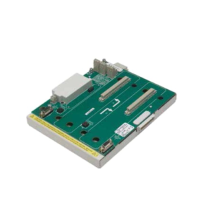
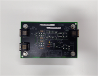
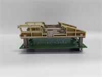
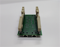
Walking into a control room with a tripped turbine usually means one thing: someone kicked a cable loose or a terminal board cooked itself in the summer heat. The GE IS200ISBBG2AAB is the workhorse I’ve pulled out of dusty Mark VIe cabinets more times than I can count. It’s not flashy. It doesn’t have “smart” diagnostics that talk to your phone. It just sits there, taking 24V signals from pressure switches and temp sensors, and passing them to the processor without complaining—unless you wire it wrong.Engineers stick with this specific revision because it handles the electrical noise in a gas turbine enclosure better than the earlier “F” or “H” revisions we saw fail during commissioning. You get 40 reliable points of isolation, which matters when a 480V VFD starts screaming nearby. The build quality is heavy-duty, typical GE industrial gear from the mid-2000s that was designed to last 20 years. Just don’t expect it to be hot-swappable in a live simplex system without causing a glitch; this board demands respect during installation.
Quality SOP & Tech Pitfalls (The Reality Check)
The Lab Report (SOP)
Before we ship an IS200ISBBG2AAB, my team runs a strict protocol. We start with a visual inspection under magnification to spot counterfeit solder joints or cracked traces—common on boards pulled from scrap yards. Next, it goes onto our Mark VIe test rack where we simulate all 40 channels using a calibrated signal generator. We verify insulation resistance with a Megger (set low, 250V DC) to ensure no moisture ingress. Finally, we log the hardware revision stamps against GE’s official compatibility matrix and seal it in an ESD-safe bag with desiccant. We use Fluke 117s for continuity checks; if the loop resistance spikes, the board gets scrapped.
The Engineer’s Warning (Pitfalls)
Here is where people get burned. The ISBB board looks identical to the TMR (Triple Modular Redundant) versions, but the pinout is different. I once watched a junior tech force a simplex board into a TMR slot because he didn’t check the suffix. The result? A shorted backplane and a three-day outage while GE sent a replacement chassis. Also, these boards are notoriously sensitive to ground loops. If you don’t bond the cabinet ground to the board mounting rail within 0.1 ohms, you’ll get phantom trips that drive everyone crazy. Always check your grounding strap before blaming the logic.
Installation & Configuration Guide
Time Estimate: 30 Minutes (Swap)
- Pre-Installation Safety ⚠️
- Perform a full system shutdown if possible. In simplex systems, hot-swapping I/O boards often triggers a nuisance trip.
- Wait 30 seconds after power removal for capacitors to discharge.
- Critical: Take high-resolution photos of the existing wiring diagram and the physical terminal block layout. One swapped wire means a failed startup.
- Removal
- Label every wire ferrule with a permanent marker. Do not trust the old tags; they fade.
- Release the DIN-rail locking clips gently. These plastic tabs become brittle after 10 years in hot cabinets. Snap one, and you’re fabricating a bracket.
- Slide the board out horizontally. Do not wiggle it vertically; you risk bending the backplane pins.
- Installation
- Copy DIP/Jumper Settings: This step prevents 90% of startup failures. The ISBBG2AAB often has factory-set jumpers for termination or voltage selection. Match them exactly to the old board.
- Seat the module firmly until you hear the backplane connector click.
- Re-terminate wires according to your photos. Torque terminals to 0.5 Nm. Overtightening strips the threads; undertightening causes arcing.
- Power-On & Testing
- Verify 24V DC presence at the main bus before engaging the board.
- Power up the controller. Watch the LED sequence: Power (Green) should be steady, Fault (Red) should be off.
- Force a test signal on channel 1 and verify the state change in the ToolboxST software. If it doesn’t register, check your common ground immediately.
IS200ISBBG2AAB GE
Compatible Replacement Models
- ✅ Drop-in Replacement: IS200ISBBG1AAB or IS200ISBBG3AAB.
- Note: These are earlier/later revisions of the same board. Functionally identical for 99% of applications. Verify firmware compatibility with your specific Mark VIe service pack level.
- ⚠️ Software Compatible: IS200ISBAG1AAB (Analog version).
- Warning: Physically fits, but logic will fail. Requires complete I/O reconfiguration in ToolboxST. Do not use unless upgrading system capability.
- ❌ Hardware Mod Required: IS200ISBDG1AAB (TMR Version).
- Advice: Different backplane pinout. Requires chassis modification and redundant wiring. Only attempt during a full control system overhaul.
Frequently Asked Questions (FAQ)
Can I hot-swap this board while the turbine is running?
Technically, the connector allows it, but I wouldn’t risk it on a Simplex system. Unlike TMR setups where two other boards hold the vote, pulling the only ISBB board breaks the circuit instantly. You will trip the machine. Plan a shutdown window.My old board has a suffix “AA” and the new one is “AB”. Will it work?
Yes. GE uses those last two letters for minor component changes or supplier shifts. As long as the base model is IS200ISBBG2, the form factor and pinout remain unchanged. I’ve mixed “AA” and “AC” revisions in the same rack with zero issues.Why are the LEDs flashing red even after wiring?
Check your 24V supply polarity. These boards don’t have reverse polarity protection on the field side. If you swapped positive and negative, you might have blown the input optocouplers. Also, verify the backplane seating; a half-seated board often throws a “Comm Fail” that looks like a hardware fault.Is this board compatible with Mark V systems?
No. Absolutely not. Mark V used a completely different architecture (often analog cards or different digital buses). Trying to force this into a Mark V panel is physically impossible and electrically dangerous. This is strictly for Mark VIe.How do I know if the board is genuine GE and not a refurb?
Look at the solder mask color and the font on the silkscreen. Counterfeits often use a slightly greener mask and blurry text. Genuine GE boards from this era have a very specific matte finish and crisp, laser-etched serial numbers. If the price seems too good to be true, it’s likely a cleaned-up scrap board that will fail in six months.