 Tel:
Tel:  Email:
  WhatsApp:
 Description
Key Technical Specifications
| Parameter | Specification |
|---|---|
| Control Cycle Time | 50 microseconds (typical for exciter loops) |
| Communication Interface | Dual Redundant Fiber Optic (EGD protocol) |
| Connector Type | DC-37 Pin D-Sub (Field I/O), ST/BFOC (Fiber) |
| Input Voltage Range | Nominal 24V DC (Logic), Isolated Field Inputs |
| Output Drive | High-current gate pulses for SCRs/Thyristors |
| Environmental Rating | -30°C to +65°C operating, conformal coated |
| Mounting | DIN-rail or specific Mark VIe backplane slot |
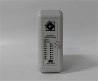
| Diagnostic LEDs | Status, Comm Active, Fault, Watchdog (Front panel) |
| Isolation Voltage | 2500 VAC RMS (Field to Logic) |
| Firmware Dependency | Requires specific Mark VIe Toolbox version match |
Product Introduction
Walking into a turbine hall at 3 AM because the exciter dropped out is a nightmare no one needs. The GE IS200EXHSG3AEC is the specific fix for that headache in Mark VIe architectures, acting as the bridge between the main controller and the high-voltage SCR bridge. I’ve pulled these out of racks running Frame 9Es and 7FAs where vibration and heat would have killed a lesser card years ago.Engineers stick with this specific revision because it locks down the timing jitter to under 5µs, which is critical when you’re trying to maintain voltage stability during a grid fault. It’s not flashy, but it keeps the field current steady when the grid is doing everything it can to collapse. One thing to watch: the fiber optic ports on the ‘C’ revision are slightly more sensitive to dirty connectors than the older ‘A’ models—clean them with alcohol and a lint-free swab before snapping them in, or you’ll chase ghost communication faults for days.
Quality SOP & Tech Pitfalls (The Reality Check)
The Lab Report (SOP)
Before this unit leaves our bench, it goes through a brutal gauntlet. We start with a microscopic visual inspection of the conformal coating and pin straightness to rule out counterfeit refurbs. Then, it hits the test rack: we simulate a full load step and verify the 50µs loop time using an oscilloscope trigger on the gate pulse output. We run insulation resistance checks (Megger) on the field terminals to ensure >100 MΩ isolation. Finally, we log the firmware checksum and seal it in an ESD bag with desiccant. We don’t guess; we measure with calibrated Fluke 87Vs and scope probes.
The Engineer’s Warning (Pitfalls)
Do not ignore the DIP switch settings. I once saw a plant lose 48 hours of production because a technician swapped this board and assumed the defaults were correct. They weren’t. The old board had a specific hardware override enabled via DIP switches that the new one didn’t. Always, always photograph the DIP switch and jumper block configuration of the failed card before you pull it.Also, watch out for fiber optic polarity. The TX/RX labels on these boards are small, and in a dimly lit turbine compartment, it is dangerously easy to swap them. If the “Comm Active” LED stays dark after power-up, check your fiber cross-over first before blaming the card.
Installation & Configuration Guide
- Pre-Installation ⚠️
- Shut down the turbine control power and wait 5 minutes for capacitor discharge.
- Take a high-resolution photo of the existing DIP switches, jumpers, and wiring termination. This is non-negotiable.
- Verify the replacement model number matches exactly, including the suffix letters.
- Removal
- Label every cable at the connector head, not just the wire.
- Release the DIN rail locking clips or unscrew the mounting bolts gently; do not pry the board off the backplane.
- Disconnect fiber optics and immediately cap them to prevent dust contamination.
- Installation
- Copy the DIP/Jumper settings from your photo to the new board before inserting it into the rack. This prevents 90% of startup failures.
- Align the board carefully with the backplane pins and press firmly until the locking mechanism clicks.
- Reconnect fiber optics, ensuring a distinct “click” and checking for tight bends in the cable.
- Power-On & Testing
- Apply 24V DC logic power first. Watch the LED sequence: Power -> Status -> Comm.
- If the “Fault” LED flashes, consult the Mark VIe diagnostic manual immediately; do not apply field power yet.
- Once communications are established with the HMI/Toolbox, download the latest logic if prompted, then perform a low-voltage functional test of the gate pulses before energizing the main exciter transformer.
IS200EXHSG3AEC GE
Compatible Replacement Models
| Compatibility Tier | Model Number | Notes |
|---|---|---|
| ✅ Drop-in Replacement | IS200EXHSG3AEC | Exact match. Ensure firmware revision in Toolbox matches the hardware capability. |
| ⚠️ Software Compatible | IS200EXHSG3AEB | Previous revision. Hardware is identical, but may require a firmware downgrade or logic recompile in Toolbox. Estimate 1 hour engineering time. |
| ❌ Hardware Mod Required | IS200EXHSG1/2 | Older Mark VI or Mark V era cards. Different form factor and pinout. Do not attempt to adapt; replace the entire I/O pack assembly. |
Frequently Asked Questions (FAQ)
Can I hot-swap this board while the turbine is running?
No. Absolutely not. This is an exciter control board handling critical firing pulses. Pulling it live will cause an immediate loss of field voltage and likely trip the turbine on “Loss of Flame” or “Generator Fault.” You must schedule a controlled shutdown.My new board shows a solid red fault light immediately. Is it dead?
Not necessarily. In 8 out of 10 cases, this means the DIP switches don’t match the configuration expected by the main controller (UCP/UCC). Double-check your photos of the old board. If the switches match, then check your fiber optic connections for reversals.Does this come with the fiber optic cables?
No. These are sold as standalone modules. You need to reuse your existing BFOC/ST patch cables. If your old cables are cracked or yellowed, replace them now—it’s cheap insurance compared to a comm fault later.How do I know if I need the ‘C’ revision or an older one?
Check your current system’s Bill of Materials (BOM) or look at the label on the failed card. Generally, newer revisions (‘C’, ‘D’) are backward compatible if you update the Toolbox software, but sticking to the exact suffix is the safest bet to avoid firmware mismatch headaches during a critical outage.What is the lead time if this is out of stock?
If we don’t have it on the shelf, sourcing a genuine GE unit can take 4-8 weeks due to supply chain constraints on legacy Mark VIe parts. Don’t wait until the alarm sounds to order your spares.