
 Tel:
Tel:  Email:
  WhatsApp:
 Description
Key Technical Specifications
| Parameter | Specification |
|---|---|
| Manufacturer | General Electric (GE) |
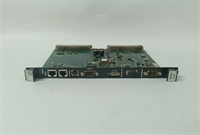
| Part Number | IS200EROCH1ABB |
| System Series | Speedtronic Mark VIe |
| Function | Emergency Overspeed Relay Output (ERO) |
| Redundancy Architecture | TMR (Triple Modular Redundant) Voting |
| Output Type | Dry Contact Relay / Solid State Switch (Configurable) |
| Load Capacity | Typically 2A @ 24V DC per channel (Verify load calc) |
| Trip Time | < 5 milliseconds (Hardware level) |
| Input Voltage | 24 VDC nominal (via backplane) |
| Operating Temp | -30°C to +65°C (-22°F to +149°F) |
| Safety Rating | SIL 2 / SIL 3 capable (System dependent) |
| Mounting | Mark VIe Backplane (VDIM slot compatible) |
| Firmware | Version locked to system build (Check GEH-6721) |
Product Introduction
When a turbine spins at 3,600 RPM and something goes wrong, you have milliseconds before catastrophic failure. The IS200EROCH1ABB isn’t just another I/O card; it’s the last line of defense. I’ve seen control processors freeze and networks lag, but this board is designed to trip the machine even if the rest of the rack is dead. It sits in the safety-critical loop, monitoring speed signals and physically opening the circuit to the emergency stop solenoids. If this board fails to operate, you don’t just have downtime; you have an insurance claim.The reason plants keep these in stock is the TMR architecture. It uses three independent channels to vote on a trip signal. Two out of three say “stop,” and the fuel cuts. No software delays, no network handshakes. The “ABB” suffix indicates a specific hardware revision that tightened up the noise immunity on the relay drivers. I’ve installed these in coal plants choked with dust and gas turbines vibrating like jackhammers. They are bulky and expensive, but compared to the cost of a thrown blade, they’re a bargain. Just don’t expect it to be plug-and-play without checking your logic solver settings first.
Quality SOP & Tech Pitfalls (The Reality Check)
The Lab Report (SOP)
We treat ERO boards like live explosives because, functionally, they are.
- Visual Inspection: We look for stress cracks around the relay sockets and signs of arcing on the terminal blocks. Counterfeit checks focus on the date codes of the internal relays.
- Live Trip Test: On our test bench, we simulate an overspeed signal. We measure the time from signal input to relay drop-out using a high-speed oscilloscope. It must be under 5ms.
- Voting Logic Verification: We disable one channel intentionally to ensure the remaining two still trip the output. Then we disable two to ensure it doesn’t trip (fail-safe mode).
- Coil Drive Check: Using a Fluke 87V, we verify the output voltage sag under load to ensure it can pull in the external emergency solenoids.
- Sealing: Anti-static packaging with humidity indicators. These boards hate moisture.
The Engineer’s Warning (Pitfalls)
The number one killer of these boards isn’t age; it’s external wiring faults. If your field wiring to the emergency solenoid has a short or a ground fault, the surge back into the ERO card can fry the output drivers instantly. I once saw a whole rack of EROs cooked because a tech didn’t check the insulation resistance on the field cables before connecting a new board. Always megger your field wiring first.Also, beware of the “Silent Fail.” Sometimes the board looks healthy, LEDs are green, but the internal voting logic is stuck due to a firmware mismatch with the main processor. If you swap this board during a startup and the turbine refuses to reset the trip, check the firmware version against the system backup immediately. Don’t just keep swapping hardware; check the code.
Installation & Configuration Guide
Time Estimate: 45 Minutes (Safety checks take time)
- Pre-Installation ⚠️
- CRITICAL: Ensure the turbine is in a safe shutdown state and the Emergency Stop (E-Stop) circuit is bypassed or isolated according to site safety procedures. You do not want to trip the machine accidentally during install.
- Document all existing jumper settings and DIP switch positions. Take photos.
- Verify the replacement part number matches exactly, including the suffix.
- Removal
- Disconnect field wiring from the terminal block. Label every wire clearly (e.g., “Trip Solenoid A+”, “Common”).
- Unscrew the terminal block if removable, or disconnect wires one by one if hard-wired to the card edge.
- Release the card retention mechanism and slide the module out smoothly.
- Installation
- Copy Settings: Transfer all jumpers and DIP switches from the old board to the new IS200EROCH1ABB. A missing jumper here means the voting logic won’t work.
- Align the card with the backplane guides and push firmly until seated.
- Reconnect field wiring. Torque terminals to spec (usually 5-7 in-lbs). Loose wires cause heat and fires.
- Power-On & Testing
- Do not energize the turbine yet. Perform a “Loop Check.”
- Apply 24V DC control power. Verify the “Healthy” LED is solid green.
- Use the engineering workstation to force a test trip signal. Watch the external multimeter on the output circuit confirm the relay opens.
- Reset the system and verify the “Ready” status before clearing the safety bypass.
IS200EROCH1ABB GE
Compatible Replacement Models
| Compatibility Tier | Model Number | Notes |
|---|---|---|
| ✅ Drop-in Replacement | IS200EROCH1ABB | Exact match. Preferred for maintaining current system certification. |
| ⚠️ Software Compatible | IS200EROCH1ABC | Newer revision. Hardware fits, but requires firmware synchronization with the Main Processor. May need a logic recompile. |
| ❌ Hardware Mod Required | IS200EROCH1A | Older revision. Pinout may differ slightly, or voltage thresholds might be incompatible with modern solenoids. Not recommended. |
Frequently Asked Questions (FAQ)
Can I test the trip function without actually shutting down the turbine?
No. This is a hard-wired safety device. If the logic says “trip,” the fuel cuts. Some systems have a “Test Mode” in the software that simulates the signal internally without opening the relay, but you must verify this feature exists in your specific logic build before attempting. Never assume.Why does the board have three sets of inputs?
That’s the TMR (Triple Modular Redundancy). It takes speed signals from three independent probes. The board votes on them. If one probe fails high, the other two override it, preventing a false trip. If two fail high, it trips to protect the machine. It’s designed to be both safe and available.My new board shows a red “Fault” LED immediately. Is it dead?
Not necessarily. Often, it means the board detects a mismatch in the expected configuration or a missing jumper. Check your DIP switches against the old board photo. If the settings match and it still faults, then yes, it could be DOA or incompatible with your backplane voltage.How often should these be replaced?
GE doesn’t give a hard expiration date, but in harsh environments (high vibration, temperature swings), I recommend pulling them for bench testing every 5-7 years. Relays have mechanical lives. If the contact resistance gets too high, it won’t trip reliably. Preventive maintenance beats emergency repairs.Is this board SIL certified?
The board itself is built to SIL standards, but the system certification depends on the entire architecture, including your sensors, wiring, and logic solver. Installing a SIL-capable board in a non-SIL configured system doesn’t magically make the whole thing SIL 3. Check your safety manual.


