
 Tel:
Tel:  Email:
  WhatsApp:
 Description
Key Technical Specifications
- Network Protocol: IONet (GE proprietary Industrial Ethernet over TCP/IP)
- Port Configuration: Dual redundant 10/100 Base-TX Ethernet ports (RJ45)
- Max Node Address: 63 remote racks per controller network
- Scan Rate: Configurable down to 5ms for critical control loops
- Input Voltage: 24V DC nominal (Range: 18–32V DC)
- Power Consumption: Approx. 3.5 Watts typical (varies with network load)
- Isolation: 1500V RMS Ethernet port isolation (protects against lightning surges)
- LED Indicators: Link/Activity, Fault, Network Status, Power OK
- Environmental Rating: Conformal coated (Class G1/G2) for harsh industrial atmospheres
- Mounting: Standard Mark VIe 21-slot or 12-slot expansion chassis
- Firmware Compatibility: Requires Mark VIe Toolset (ToolboxST) v4.x or higher
- Redundancy: Supports network redundancy (A/B channels) for zero-downtime comms
Product Introduction
If your turbine control system can’t talk to its remote I/O racks, you’re flying blind. The GE IS200ERIOH1AAA is the workhorse that keeps that conversation alive in environments where standard Cisco switches would melt. I’ve seen these modules sitting in racks next to 400°F steam lines, covered in oil mist, yet still pushing data packets without a hiccup. It’s not just a network card; it’s the nervous system connecting your main processor to the field sensors that decide whether the machine runs or trips. Without a functioning ERIO, your $50 million asset is just a very expensive paperweight.The “H1” revision is the one you want in your spares cabinet. Earlier versions had occasional issues with packet loss during high electrical noise events, but GE tightened up the shielding and firmware logic here. You get dual-port redundancy that actually works—if one cable gets chewed by a rat or cut by a fork lift, the system swaps to the backup port faster than a human eye can blink (typically <50ms). One caveat: this board is extremely sensitive to IP address conflicts. I’ve wasted entire weekends chasing “ghost” faults only to find a laptop plugged into the maintenance port with a static IP that clashed with the rack. Double-check your addressing scheme before you power up.
Quality SOP & Tech Pitfalls (The Reality Check)
The Lab Report (SOP)
We don’t just plug it in and hope. Every IS200ERIOH1AAA undergoes a visual inspection for cracked RJ45 jacks—a common failure point from rough handling. Then, we hook it up to a simulated Mark VIe controller on our test bench, flooding the IONet with traffic to stress-test the buffer capacity. We verify both ‘A’ and ‘B’ network ports independently, ensuring failover happens within spec. A Megger test checks isolation resistance on the power inputs, and we log the MAC address to ensure it hasn’t been cloned or tampered with. Finally, it’s sealed in an ESD bag with humidity indicators. We use a Fluke Network Tester to certify the cable integrity before even connecting the board.The Engineer’s Warning (Pitfalls)
The number one killer of these boards isn’t heat; it’s bad grounding and network loops. If you daisy-chain switches incorrectly or create a ground loop between the controller and the remote rack, you’ll induce voltage spikes that fry the Ethernet transformers instantly. I recall a site in Louisiana where they installed three new ERIO boards in a month, all failing within days. Turns out, their “grounded” conduit was actually carrying 12V of stray current from a nearby VFD. The other major pitfall is ignoring the dip switches for node addressing. If you set the wrong binary address, the main controller won’t see the rack, and you’ll spend hours troubleshooting a “broken” board that’s just misconfigured. Always verify the node switch settings against the electrical schematic before installation.
Installation & Configuration Guide
Phase 1: Pre-Installation
⚠️ SHUT DOWN NETWORK POWER. Disconnect 24V DC to the expansion rack. Wait 15 seconds for capacitors to discharge.
⚠️ DOCUMENT SETTINGS. Photograph the existing DIP switch settings for the node address. Note the specific Ethernet port usage (Port A vs. Port B) and cable routing.Phase 2: Removal
Label both Ethernet cables clearly (e.g., “IONet A – To Controller”). Unclip the locking tab on the RJ45 connectors gently; plastic tabs become brittle in hot panels. Remove the mounting screws or release the DIN rail clips. Slide the module out straight to avoid bending the backplane pins.Phase 3: Installation
SET NODE ADDRESS FIRST. Before seating the new IS200ERIOH1AAA, configure the DIP switches to match your photos exactly. An incorrect address will prevent communication entirely. Seat the module firmly until it locks. Reconnect Ethernet cables to the correct ports (A to A, B to B). Ensure cables are routed away from high-voltage lines to minimize EMI.Phase 4: Power-On & Testing
Restore 24V DC power. Observe the LED sequence: The “PWR” LED should be solid green. The “LINK” LEDs on the active Ethernet ports should illuminate. The “NET” or “COMM” LED should flash indicating activity. Open ToolboxST and verify the expansion rack appears online with no communication faults. Perform a forced I/O toggle test from the HMI to confirm data integrity across the network.
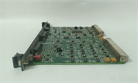
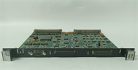
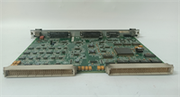
IS200ERIOH1AAA GE
Compatible Replacement Models
- ✅ Drop-in Replacement: IS200ERIOG1AAA – Previous revision. Functionally identical for most applications, but may require a firmware update to match the latest ToolboxST projects. Often available at a lower cost.
- ⚠️ Software Compatible: IS200ERIOH1ABA – Same hardware platform with minor component sourcing changes (e.g., different Ethernet transformer vendor). Requires verifying compatibility in the GE Project Properties. Expect 10-15 mins for firmware verification.
- ❌ Hardware Mod Required: IS200TCIOH1A – This is a Terminal Board, not a communication module. It physically fits some chassis but serves a completely different purpose. Do not attempt to use as a substitute.
Frequently Asked Questions (FAQ)
Can I replace this board while the turbine is running?
Generally, no. While the Mark VIe system has redundancy, removing the ERIO board breaks the communication link to all I/O in that specific expansion rack. If those I/O points are critical for protection (like vibration or flame detection), the turbine will trip. Only attempt a hot-swap if you have confirmed with your logic engineer that the specific rack contains non-critical I/O and your system is fully redundant.Why are my “Link” LEDs off even though the cables are plugged in?
First, check the cable integrity with a tester; industrial Ethernet cables take a beating. Second, verify the switch port configuration on the upstream network switch—it must be set to auto-negotiate or match the 10/100 Mbps speed manually. Third, ensure the board has valid 24V power; the Ethernet transceivers won’t activate without it. If all else fails, the RJ45 jack on the board might be damaged.Is this compatible with standard Modbus TCP networks?
No. The IS200ERIOH1AAA speaks GE’s proprietary IONet protocol. It cannot communicate directly with standard Modbus TCP devices or third-party PLCs without a gateway or specific translation layer in the main controller. Don’t try to plug it into a generic office switch expecting it to talk Modbus.How do I determine the correct node address?
The node address is set via the DIP switches on the front of the board. It corresponds to the rack number defined in your ToolboxST project file. Refer to the electrical schematic for the specific expansion rack you are servicing. Setting the wrong address will cause a “Node Missing” fault in the controller.What does it mean if the “Fault” LED is solid red?
A solid red Fault LED usually indicates a hardware failure internal to the board or a severe configuration mismatch (like a firmware version conflict). Check the controller diagnostic alarms in ToolboxST for specific error codes. If the board fails self-test upon power-up, it likely needs replacement. Don’t ignore it; a faulty comms board can lead to lost control signals.


