 Tel:
Tel:  Email:
  WhatsApp:
 Description
Key Technical Specifications
- Input Voltage: 24V DC nominal (Range: 18–32V DC)
- Architecture: TMR (Triple Modular Redundant) for SIL-3 compliance
- Trip Response Time: < 35ms (from signal exceedance to relay de-energize)
- Overspeed Setpoint: Configurable via DIP switches or ToolboxST (typically 110% rated speed)
- Input Signal Type: Magnetic Pickup (MPU) or Proximity Probe (75mV – 200V pk-pk)
- Number of Inputs: 3 independent channels (one per redundant lane)
- Output Relays: 3 Form-C dry contacts (rated 5A @ 250V AC)
- Operating Temperature: -30°C to +65°C (-22°F to +149°F)
- Storage Temperature: -40°C to +85°C
- Humidity: 5% to 95% non-condensing
- Isolation: 1500V AC between field inputs and logic
- Diagnostic Coverage: >99% self-checking (watchdog timers, memory parity)
Product Introduction
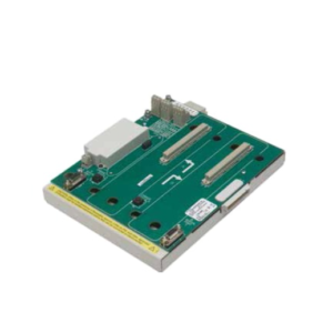
When a gas turbine hits 115% speed, you don’t have time for a software scan cycle or a network handshake. You need iron-clad, hardware-based logic that cuts fuel immediately. That is exactly what the GE IS200ERDDH1ABA does. I’ve seen main controllers freeze up during electrical storms, but this ERDD board? It just sits there, watching the magnetic pickups, ready to slam the trip relays open in under 35 milliseconds. It’s the last line of defense between a controlled shutdown and a catastrophic explosion.Engineers specify this H1 revision because it fixed the noise susceptibility issues we saw in the early “E” and “F” versions. In high-vibration environments near the turbine base, earlier boards would occasionally false-trip due to EMI from ignition systems. The H1 revision tightened the input filtering without slowing down the response. It’s not a module you want to cheap out on. If you buy a refurb without a calibration certificate, you’re gambling with a multi-million dollar asset. Treat this board with the same respect you’d give a live grenade.
Quality SOP & Tech Pitfalls (The Reality Check)
The Lab Report (SOP)
Testing an ERDD board isn’t like checking a standard I/O card. We don’t just toggle bits. First, we perform a visual inspection for heat stress on the relay coils—a common sign of previous field use. Then, we mount it on a TMR test rack and inject precise frequency signals simulating 100%, 109%, and 111% speed using a Fluke 8060A function generator. We measure the exact trip time with a digital oscilloscope; if it exceeds 35ms, the board fails. We also verify the “voting” logic by disabling one channel to ensure the other two still hold the turbine running. Finally, we log the firmware checksum and seal it in anti-static packaging with a humidity indicator.
The Engineer’s Warning (Pitfalls)
The biggest mistake I see? Ignoring the shield grounding on the magnetic pickup cables. The ERDD is incredibly sensitive to noise. If you run your MPU cables next to VFD power lines without proper shielding, you’ll get false overspeed trips. I once spent four hours troubleshooting a “bad board” only to find the tech had left the cable shield floating at the junction box. Another disaster zone: the DIP switches. These set the overspeed threshold. If you don’t photograph and double-check these settings against the engineering spec sheet before installation, you might set the trip point to 90% instead of 110%. The turbine won’t even start. Always, always verify the switch positions.
Installation & Configuration Guide
Time Estimate: 45 Minutes (Critical Safety Device)
- Pre-Installation Safety ⚠️
- Lockout/Tagout (LOTO): Isolate all turbine control power. This is a safety-critical component; accidental activation during wiring is unacceptable.
- Wait 60 seconds for capacitor discharge.
- Critical: Photograph the DIP switch settings and jumper positions on the old board. Verify these against the site’s specific protection logic diagram. Do not trust memory.
- Removal
- Label every wire at the terminal block. Use permanent markers on fresh tape.
- Release the DIN-rail clips carefully. These boards are heavier than standard I/O due to the relays; support the weight while unclipping to avoid dropping it onto the backplane pins.
- Slide straight out. Do not twist.
- Installation
- Set DIP Switches: Before seating the board, configure the new IS200ERDDH1ABA DIP switches to match your photos exactly. A single switch in the wrong position changes the trip logic or voltage threshold.
- Seat the module firmly into the TMR backplane. Ensure the locking mechanism engages.
- Re-terminate wires. Torque terminals to 0.6 Nm. Loose connections on safety circuits are a leading cause of intermittent faults.
- Power-On & Testing
- Apply 24V DC. Verify the “Power” LED is solid green on all three redundant lanes.
- Check the “Fault” LEDs. They should be off. If red, check the backplane seating and DIP switch configuration.
- Functional Test: Do not skip this. Use a signal generator to simulate an overspeed condition (e.g., 112% frequency). Verify that the output relays de-energize and the turbine trip circuit opens. Confirm the trip time is within spec (<35ms).
IS200ERDDH1ABA GE
Compatible Replacement Models
- ✅ Drop-in Replacement: IS200ERDDH1ABB or IS200ERDDH1ABC.
- Note: Later suffix revisions. Pinout and logic are identical. These often include updated internal components for better longevity. Direct swap.
- ⚠️ Software Compatible: IS200ERDDG1ABA (Previous Revision).
- Warning: Physically compatible, but may require firmware updates in the main controller to recognize diagnostic codes correctly. Expect 1-2 hours of engineering time for verification.
- ❌ Hardware Mod Required: IS200ERDSH1ABA (Simplex Version).
- Advice: Different form factor and lack of TMR voting logic. Cannot be used in a TMR Mark VIe panel without rewiring the entire safety chain and modifying the chassis. Strongly advise against; compromises safety integrity level (SIL).
Frequently Asked Questions (FAQ)
Can I replace this board while the turbine is running?
No. Absolutely not. This is part of the emergency trip circuit. Removing it breaks the redundancy and likely triggers an immediate turbine trip. Even if it doesn’t trip instantly, you are operating without overspeed protection, which violates almost every insurance policy and safety regulation worldwide. Schedule a shutdown.What does the “H1” in the model number mean?
It indicates the hardware revision. The “H” series fixed specific noise immunity issues found in earlier “E” through “G” revisions. If your panel originally had “E” boards and you’re replacing one, I highly recommend upgrading all three channels to “H1” to prevent mismatched diagnostic behaviors, though a single swap will work electrically.My new board shows a red “Fault” LED immediately after power-up.
90% of the time, this is a DIP switch setting error. The ERDD performs a self-check on startup; if the switch configuration doesn’t match the expected logic (e.g., invalid voltage range selected), it flags a fault. Double-check every switch against the old board. If switches are correct, you might have a bent pin on the backplane connector.Is this board calibrated at the factory?
Yes, the hardware thresholds are set at the factory. However, the application (the specific RPM trip point) is determined by the DIP switches and the input frequency scaling in the controller. You do not need to send it back to GE for calibration unless the physical components have been damaged. Just verify the settings match your site data.Why is the price so much higher than a standard I/O board?
Because it’s a safety-critical device with Triple Modular Redundancy (TMR). You aren’t just buying a circuit board; you’re buying three independent processing lanes, high-reliability relays, and extensive self-diagnostics designed to meet SIL-3 standards. Cheap alternatives don’t exist for this function. If you see a “bargain” ERDD board, check the date code—it’s likely pulled from a scrapped unit with unknown relay wear.