
 Tel:
Tel:  Email:
  WhatsApp:
 Description
Key Technical Specifications
- Input Voltage Range: 90–264 VAC or 100–300 VDC (Universal Wide Range)
- Input Frequency: 47–63 Hz (AC Input)
- Output 1 (Logic): 5.0 VDC ±2% @ 20 Amps (100 Watts)
- Output 2 (Field/Relay): 24.0 VDC ±5% @ 5 Amps (120 Watts)
- Total Power Rating: 220 Watts Maximum Continuous
- Hold-Up Time: >20ms at full load (prevents brownout trips)
- Operating Temperature: -30°C to +65°C (-22°F to +149°F)
- Efficiency: >85% typical at 50% load
- Protection: Over-voltage, Over-current, Short-circuit, Thermal shutdown
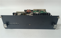
- Connector Type: Terminal block for AC/DC input; 37-pin DIN for backplane
- LED Indicators: AC OK, 5V OK, 24V OK, Fault/Trip
- Mounting: DIN Rail compatible with Mark VIe chassis slots
Product Introduction
Power supplies are the heart of the control system, and when they fail, everything stops. The IS200EPSMG2AEC isn’t just a box that changes voltage; it’s the buffer between your dirty facility power grid and the sensitive logic boards running your turbine. I’ve seen cheap aftermarket supplies ripple so hard they caused random controller resets during startup sequences. This GE unit handles the spikes from large motor starts and welding equipment in the same plant without flinching.The reason plants keep these in stock is the dual-rail stability. It delivers a rock-solid 5V for the CPU logic and a separate 24V for relays and solenoids, keeping electrical noise from the high-current side from corrupting data on the low-voltage side. The ‘C’ revision specifically improved the thermal management on the rectifier bridge. One warning though: These units are picky about grounding. If your chassis ground isn’t under 1 Ohm, you might get nuisance “Fault” LEDs even if the output voltage is perfect. Check your ground strap first before swapping the card.
Quality SOP & Tech Pitfalls (The Reality Check)
The Lab Report (SOP)
We don’t just plug it in and hope. Here is our checkout protocol:
- Visual & Mechanical: Inspect the terminal blocks for heat discoloration (sign of loose wires in previous life) and verify the 37-pin backplane connector has no bent pins.
- Load Bank Test: We connect the unit to a programmable electronic load. We ramp the 5V output from 0A to 20A while monitoring ripple. It must stay under 50mV peak-to-peak.
- Brownout Simulation: Using a variac, we drop the input voltage to 85VAC to ensure the unit shuts down gracefully without latching up or sending bad voltage to the backplane.
- Thermal Imaging: Run at 80% load for 1 hour. We use a FLIR camera to check for hot spots on the MOSFETs. Anything over 85°C internal case temp gets flagged.
- Final Log: Record serial number and output calibration values before anti-static bagging.
The Engineer’s Warning (Pitfalls)
Never ignore the “Inrush Current” rating. I once saw a main breaker trip instantly upon installing a new EPSM because the technician didn’t realize the cold start inrush could hit 40A for a few milliseconds. If your branch circuit breaker is sized too tight (e.g., exactly at the running current), it will pop every time you swap a card. You need a slow-blow characteristic or a slightly higher rating to handle the startup surge.
Also, watch the polarity on the DC input option. While the unit accepts DC input, reversing the polarity on the terminal block will destroy the input bridge rectifier instantly. It’s not fused internally for reverse polarity. Double-check your multimeter before tightening those terminals.
Installation & Configuration Guide
Time estimate: 20 minutes (plus safety lockout time).
- Pre-Installation
- ⚠️ LOCKOUT/TAGOUT: De-energize the entire control cabinet. There is no safe way to “hot-swap” the primary power supply in a non-redundant configuration. Even in redundant pairs, isolate the specific feeder.
- Wait 2 minutes for capacitors to discharge. Verify 0V at the input terminals with a Fluke 115.
- Photo Documentation: Take a picture of the wiring diagram on the cabinet door and the existing wire labels.
- Removal
- Loosen the terminal block screws. Remove wires one by one and label them immediately if tags are missing.
- Release the DIN rail locking lever at the bottom of the module.
- Tilt the module outward and lift off the backplane connector.
- Installation
- Inspect Terminals: Ensure no stray wire strands are sticking out of the ferrules. A single strand touching the chassis causes a short.
- Seat the new IS200EPSMG2AEC onto the backplane connector first, then push down until the DIN clip locks.
- Re-connect wires strictly according to your photo labels. Torque terminals to 0.5 Nm. Do not overtighten; you will strip the threads.
- Power-On & Testing
- Remove lockout devices and energize the input.
- LED Check: “AC OK” should light immediately. “5V OK” and “24V OK” should follow within 2 seconds.
- Voltage Verification: Measure the output at the terminal block. Adjust the trim pot (if accessible on this revision) only if voltage is outside the 4.9-5.1V range. Usually, factory setting is perfect.
- Monitor the controller reboot sequence. If the CPU doesn’t boot, check the 5V rail under load.
IS200EPSMG2AEC GE
Compatible Replacement Models
| Model Number | Compatibility Tier | Notes |
|---|---|---|
| IS200EPSMG2AEC | ✅ Drop-in Replacement | Exact match. Current standard revision for most Mark VIe panels. |
| IS200EPSMG2AEB | ⚠️ Software Compatible | Older revision. Physically fits, but may have different thermal limits. Verify ambient temp requirements. |
| IS200EPSMG2AED | ✅ Drop-in Replacement | Newer revision. Enhanced efficiency. Direct swap, usually no config changes needed. |
| IS200EPSMH1Axx | ❌ Hardware Mod Required | Different form factor and pinout. Requires chassis modification. Do not attempt as a quick fix. |
Frequently Asked Questions (FAQ)
Can I replace this power supply while the turbine is running?
Only if your system is configured with fully redundant power supplies (two EPSM modules sharing the load) AND they are fed from independent sources. If you have a single supply, pulling it kills the controller. Even in redundant systems, I recommend scheduling a brief maintenance window. If one supply is already faulty, the remaining one is carrying 100% load; stressing it during a swap risks a total blackout if the second one hiccups.My “Fault” LED is on, but the output voltage measures perfectly. What gives?
This usually indicates a communication fault with the controller or a temperature warning. The EPSM talks to the CPU over the backplane. If the CPU doesn’t see the power supply ID, it flags a fault. Check if the 37-pin connector is fully seated. Also, if the internal temperature sensor reads >70°C, it will light the fault LED as a pre-warning, even if outputs are stable. Check your cabinet cooling fans.What size wire should I use for the input terminals?
For the 90-264VAC input, use minimum 14 AWG (2.5 mm²) stranded copper with ferrules. The terminal blocks are rated for up to 10 AWG, but 14 AWG is easier to terminate correctly without fraying. Never use solid core wire; vibration will fracture it inside the clamp, leading to arcing and fires.Is the 24V output isolated from the 5V output?
Yes, they are internally isolated rails, but they share a common return (ground) inside the Mark VIe backplane architecture. Do not try to float the 24V ground separately from the 5V ground in the field wiring; the backplane ties them together anyway. Doing so creates ground loops that introduce noise into the analog signals.How long does the hold-up time last during a power blip?
Specified at >20ms at full load. In the real world, I’ve seen it ride through dips of up to 40ms if the load is only at 50%. This is enough to get through most utility transfer switch operations without tripping the turbine. If your plant has frequent brownouts longer than 50ms, you need an external UPS, not just a better power supply.


