
 Tel:
Tel:  Email:
  WhatsApp:
 Description
Key Technical Specifications
| Parameter | Specification |
|---|---|
| Input Voltage Range | 90–264 VAC (47–63 Hz) OR 90–300 VDC |
| Output Voltage | 24V DC (Adjustable ±10% via trim pot) |
| Max Output Current | 10.0 Amps continuous per module |
| Redundancy Mode | Active Current Sharing (N+1 configuration) |
| Hold-up Time | >20ms at full load (prevents reset on brief dips) |
| Efficiency | >85% typical at 50% load |
| Operating Temp | -30°C to +70°C (Derate above 60°C) |
| Isolation | 3000 VAC Input-to-Output, 500 VDC Output-to-Ground |
| Protection | Over-voltage, Over-current, Thermal shutdown |
| Connectors | Terminal block (Power), 37-pin D-Sub (Comm/Monitor) |
| Mounting | Mark VIe Backplane Slot or DIN Rail Adapter |
| MTBF | >100,000 hours (calculated per Telcordia SR-332) |
Product Introduction
Power glitches are the silent killer of turbine control systems. One momentary dip in the plant bus, and if your power supply doesn’t ride through it, you’re looking at an unplanned outage and a very angry shift supervisor. The GE IS200EPSMG2ADC is the workhorse I trust to keep the Mark VIe rack alive when the grid gets dirty. It’s not just a converter; it’s the heartbeat of the control cabinet.I specify this ‘D’ revision because GE finally fixed the noisy fan circuit that plagued the early ‘A’ models. It delivers a rock-solid 24V even when two other modules are pulling heavy current during a startup sequence. The active current sharing is genuine—if one unit fails, the others pick up the load without a voltage sag greater than 2%. Just don’t expect it to tolerate wet conditions; the conformal coating is good, but I’ve seen water tracking across the terminal blocks fry these instantly. Keep the cabinet seals tight.
Quality SOP & Tech Pitfalls (The Reality Check)
The Lab Report (SOP)
We don’t just plug these in and hope. Every IS200EPSMG2ADC undergoes a load bank test where we ramp the current from 0 to 12A (120% overload) to verify the shutdown threshold triggers correctly. We measure ripple voltage with a high-bandwidth scope; anything over 50mV peak-to-peak gets rejected. We also simulate a main input dropout for 15ms to confirm the hold-up capacitors keep the output stable. Finally, we check the “Power Good” relay timing against the OEM spec sheet using a digital timer. If the relay chatters, the unit fails.
The Engineer’s Warning (Pitfalls)
The biggest mistake? Ignoring the parallel jumpers. When running these in redundant pairs or triples, you must install the specific current-sharing jumper harness between the units. I watched a junior tech install three brand-new supplies, wire them all to the same bus, and leave the share links off. Result: One unit took 100% of the load, overheated, shut down, and cascaded the failure to the next unit within seconds. Total rack blackout. Always verify the sharing harness is clipped in tight.Also, watch the input voltage selection. While these are auto-ranging for AC/DC, some older site-specific configurations used external transformers. Ensure you aren’t feeding 120V AC into a setup expecting 240V, or vice versa, based on old drawings that haven’t been updated since the 90s. Measure the incoming voltage with a Fluke 115 before flipping the breaker.
Installation & Configuration Guide
- Pre-Installation ⚠️
- Lockout/Tagout (LOTO) the main AC/DC feed to the control cabinet. Verify zero energy with a multimeter.
- Wait at least 2 minutes for internal capacitors to discharge (check LED status).
- Inspect the backplane pins for bending; a bent pin here means no power to the whole rack.
- Removal
- Disconnect the input power wires and the output distribution cables. Label them clearly (e.g., “Input L1”, “Output +24V Rack A”).
- If in a redundant setup, carefully unclip the current-sharing harness first.
- Unscrew the mounting bolts or release the retention clips and slide the module out straight.
- Installation
- Set the Output Voltage: Before installing, use a small screwdriver to adjust the trim pot to 24.0V DC while monitoring with a bench power supply if possible, or set to mid-range.
- Slide the module into the slot, ensuring the backplane connector seats fully. You should feel a firm stop.
- Reconnect the Current-Sharing Harness: This is critical for redundancy. Ensure the connector clicks into place on both modules.
- Tighten input/output terminal screws to the specified torque (usually 0.5–0.6 Nm). Loose wires cause arcing and heat.
- Power-On & Testing
- Apply input power. The green “Input OK” LED should light immediately.
- Check the output voltage at the terminals; adjust the trim pot if it deviates more than ±0.5V from 24V.
- Verify the “Power Good” relay closes (audible click) and signals the main controller.
- Under load, check that current is shared equally between parallel units (within 10% tolerance).
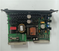
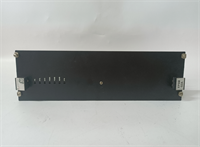
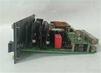
IS200EPSMG2ADC GE
Compatible Replacement Models
| Compatibility Tier | Model Number | Notes |
|---|---|---|
| ✅ Drop-in Replacement | IS200EPSMG2ADC | Exact match. Preferred for new installs due to improved thermal performance. |
| ⚠️ Software Compatible | IS200EPSMG2ADB | Previous revision. Functionally identical but may run hotter under full load. No logic changes needed. |
| ❌ Hardware Mod Required | IS200EPSMG1A | Older Mark VI non-redundant style. Different form factor and lacks current sharing pins. Requires backplane modification or adapter kit (not recommended). |
Frequently Asked Questions (FAQ)
Can I mix different revisions (e.g., Rev B and Rev C) in the same redundant bank?
Technically, yes, they will share load, but I advise against it. Different revisions often have slightly different output impedance curves. This can cause one unit to carry 70% of the load while the other idles, defeating the purpose of redundancy. Stick to matching revisions in a parallel setup.My unit is making a high-pitched whining noise. Is it failing?
If it’s a steady whine, it’s likely the switching frequency interacting with a loose component or a specific load harmonic. If it’s a grinding or rattling sound, the internal cooling fan (if equipped on your specific sub-model) is dying. Replace it soon; overheating is the fastest way to kill the electrolytic caps inside.Does this module handle 125V DC station battery inputs?
Yes. The input range covers 90-300 VDC, so it works directly off standard substation battery buses without an extra DC/DC converter. Just ensure your polarity is correct; reverse polarity protection exists, but blowing the input fuse is still a hassle you don’t need during a startup.How do I test the redundancy before relying on it?
With the system running on dual supplies, carefully pull the input fuse on one unit while monitoring the rack voltage with a scope or fast multimeter. The voltage dip should be less than 2V and recover instantly. If the rack resets, your sharing harness is bad or the second unit isn’t configured correctly. Do this test during a maintenance window, not production.What happens if the “Power Good” relay doesn’t close?
The main controller (UCP/UCC) will see a loss of power integrity and may inhibit startup or trip the turbine. Usually, this means the output voltage is out of the 20-28V window, or the internal self-test failed. Check your trim pot setting first, then suspect the internal reference circuit.


