 Tel:
Tel:  Email:
  WhatsApp:
 Description
Key Technical Specifications
| Parameter | Specification |
|---|---|
| Input Voltage Range | 90–264 VAC (47–63 Hz) OR 90–300 VDC |
| Output Voltage | 24V DC (Adjustable ±10% via trim pot) |
| Max Output Current | 10.0 Amps continuous per module |
| Redundancy Mode | Passive (Diode OR-ing required for external redundancy) |
| Hold-up Time | >20ms at full load (prevents reset on brief dips) |
| Efficiency | >84% typical at 50% load |
| Operating Temp | -30°C to +70°C (Derate above 60°C) |
| Isolation | 3000 VAC Input-to-Output, 500 VDC Output-to-Ground |
| Protection | Over-voltage latch, Over-current foldback, Thermal shutdown |
| Connectors | Terminal block (Power), 37-pin D-Sub (Comm/Monitor/Alarm) |
| Mounting | Mark VIe Backplane Slot (Single width) |
| MTBF | >95,000 hours (calculated per Telcordia SR-332) |
Product Introduction
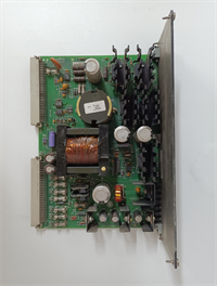
Finding a dead control rack because a single power supply failed is a classic Tuesday morning disaster in older plants. The GE IS200EPSMG1AED is the standard single-module solution for Mark VIe systems that don’t use the active current-sharing backplane of the G2 series. It’s a brute-force converter that takes whatever dirty power the plant throws at it and spits out clean 24V DC.I keep these in stock because the ‘E’ revision finally addressed the capacitor aging issues we saw in the early ‘A’ and ‘B’ units running in high-heat cabinets. It pushes a solid 10 amps without breaking a sweat, but remember: this is a “dumb” supply compared to the G2. It doesn’t talk to its neighbors to balance the load. If you run two of these in parallel without external diodes, the one with the slightly higher voltage setting will hog the entire load and burn out. It’s reliable, but only if you wire it right.
Quality SOP & Tech Pitfalls (The Reality Check)
The Lab Report (SOP)
Our testing protocol for the IS200EPSMG1AED is strict because power supplies lie until they are loaded. We hook them up to an electronic load bank and cycle from 10% to 110% capacity while monitoring ripple. We demand <60mV peak-to-peak noise; anything higher suggests failing filter caps. We simulate a brownout by dropping input voltage to 85V AC to ensure the unit shuts down cleanly rather than oscillating. Finally, we verify the “Power Good” relay logic against the datasheet timing. If the relay chatters during startup, the unit gets quarantined.
The Engineer’s Warning (Pitfalls)
Do not parallel these directly. I cannot stress this enough. Unlike the IS200EPSMG2 series, the G1 models do not have active current sharing pins. If you install two G1 units and tie their outputs together hoping for redundancy, the unit with the highest output voltage (even by 0.2V) will supply 100% of the current until it trips on thermal overload. Then the second one kicks in, overloaded, and trips too. Boom. Blackout. You must use external Schottky diodes on the output of each unit if you want a redundant setup with G1 modules.Also, check the input jumpers. While these are wide-range inputs, some legacy sites have weird grounding schemes. I once saw a G1AED fry its input bridge rectifier because the site neutral was floating 40V off ground. Always measure your incoming L-N and L-G voltages before connecting. Don’t trust the old prints; trust your multimeter.
Installation & Configuration Guide
- Pre-Installation ⚠️
- Lockout/Tagout (LOTO) the main power feed. Verify 0V at the terminals.
- Wait 3 minutes for internal capacitors to discharge. These hold a charge longer than you think.
- Inspect the backplane connector pins. Bent pins here mean no power distribution to the rack.
- Removal
- Label all input (L1, L2, N, G) and output (+24V, RTN) wires clearly.
- Disconnect the 37-pin D-Sub alarm/monitor cable carefully; the locking tabs are brittle on older cables.
- Remove mounting screws and slide the module straight out. Do not wiggle it excessively.
- Installation
- Set Output Voltage: Adjust the trim pot to 24.0V DC on the bench if possible, or set to the 12 o’clock position before installing.
- Slide the module into the slot until it seats firmly against the backplane.
- Wire External Diodes (If Redundant): If you are building a redundant pair, install Schottky diodes (e.g., 40A 100V) on the positive output of each supply before tying them together. This step is mandatory for G1 models.
- Torque terminal screws to 0.5–0.6 Nm. Loose connections cause heat spots that melt terminals.
- Power-On & Testing
- Apply input power. Verify the green “Input OK” LED illuminates.
- Measure output voltage at the terminals. Adjust the trim pot if necessary to hit 24.0V ±0.2V.
- Check the “Power Good” relay status on the HMI or with a multimeter.
- If running redundant with diodes, measure the current draw on each unit under load to ensure they are sharing (they won’t share perfectly, but neither should be at 100%).
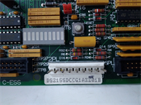
IS200EPSMG1AED GE
Compatible Replacement Models
| Compatibility Tier | Model Number | Notes |
|---|---|---|
| ✅ Drop-in Replacement | IS200EPSMG1AED | Exact match. Best choice for single-supply racks or diode-ORed redundant setups. |
| ⚠️ Software Compatible | IS200EPSMG1AEC | Previous revision. Functionally identical but may have older capacitor batches. Check date codes. |
| ❌ Hardware Mod Required | IS200EPSMG2ADC | Not a direct swap. The G2 series has active current sharing pins and different firmware expectations. Swapping G1 for G2 requires backplane wiring changes and controller config updates. |
Frequently Asked Questions (FAQ)
Can I replace a failed IS200EPSMG2ADC with this G1AED model?
No. Do not do this. The G2 series uses active current sharing signals through the backplane that the G1 series does not support or generate. Putting a G1 in a G2 slot will likely result in improper load sharing or controller faults. Stick to the exact series match unless you are upgrading the whole rack.Why is my output voltage drifting after a few hours of operation?
If the voltage drifts up or down significantly after warm-up, the internal voltage reference or the feedback optocoupler is likely failing. This is common in units that have been subjected to high heat cycles. Replace the unit; trying to tweak the trim pot is a temporary band-aid that will fail again during the next grid fluctuation.Does this unit require a specific firmware update?
No. The IS200EPSMG1AED is an analog/digital hybrid power supply. It does not run user-accessible firmware like a CPU module. However, the main controller (UCP/UCC) might need to know the power supply type for alarm masking, but generally, it just monitors the “Power Good” dry contact.How hot is too hot for these modules?
If the case temperature exceeds 70°C, you are in the danger zone. The unit will thermally derate (reduce current) to protect itself, which can cause a voltage drop under load. If your cabinet temps are consistently this high, you need better airflow or AC cooling, not just a new power supply.What size wire should I use for the 10A output?
Stick to minimum 14 AWG (2.0 mm²) for the output leads, even though 16 AWG technically carries 10A. In industrial environments, voltage drop and mechanical strength matter more. For the input side, follow your local electrical code based on the input amperage (usually 16 or 14 AWG for 120/240V AC).