 Tel:
Tel:  Email:
  WhatsApp:
 Description
Key Technical Specifications
- Input Voltage: 24V DC nominal (Range: 18–32V DC)
- Network Ports: 2x RJ45 (10/100 Base-TX), Auto-sensing
- Protocol Support: Modbus TCP (Server/Client), SRTP (Server), UDP/TCP IP
- Data Capacity: Up to 4,096 registers per map (configurable)
- Update Rate: Configurable 10ms – 1000ms (Typical field setting: 50ms)
- Operating Temperature: -30°C to +65°C (-22°F to +149°F)
- Storage Temperature: -40°C to +85°C
- Humidity: 5% to 95% non-condensing
- Isolation: 1500V AC Ethernet port isolation (prevents ground loops)
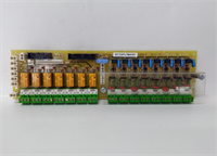
- LED Indicators: Link/Activity per port, Status, Fault, Power
- Mounting: Mark VIe DIN-rail chassis (Single slot width)
- Firmware: Flash memory upgradable via ToolboxST or FTP
Product Introduction
In modern power plants, the control room is miles away from the turbine, and everyone wants real-time data on their tablets. The GE IS200EGDMH1AFF is the bridge that makes that happen without crashing your control processor. I’ve seen plants try to hack together serial-to-Ethernet converters to save money, only to end up with data gaps every time a welder struck an arc nearby. This board is built different. It handles the electrical noise of a generator hall while pushing hundreds of data points to the DCS every second.The “H1” revision is the one you want. Earlier versions had a nasty habit of locking up if the network traffic spiked during a plant startup sequence. GE patched that in the H1 firmware and hardware combo. It’s not just a communicator; it’s a buffer that protects your critical control logic from network storms. One thing to note: this board is picky about IP conflicts. If your IT department assigns an address already in use, this module will shut its ports down faster than a bouncer at a closed club. Double-check your subnet mask before powering up.
Quality SOP & Tech Pitfalls (The Reality Check)
The Lab Report (SOP)
We don’t just plug these in and hope for the best. Our SOP starts with a visual check of the RJ45 magnetics—look for burnt pins or corroded contacts. Then, we mount the EGDM on a live Mark VIe test rack. We flood the ports with simulated DCS traffic using a packet generator to stress-test the buffer capacity. We verify the Modbus register mapping against a sample configuration file to ensure data integrity (no bit-shifting errors). Finally, we measure the update latency with a Wireshark capture; if the jitter exceeds 2ms on a 50ms scan, we reject it. We seal it with the firmware version clearly labeled on the bag.
The Engineer’s Warning (Pitfalls)
Here is the classic field disaster: The “Ghost IP.” A technician swaps a failed EGDM, copies the DIP switches (if applicable for boot mode), but forgets that the IP address is stored in the volatile configuration downloaded from the controller. If the controller isn’t online yet, the board sits there with no IP, and the operator screams that the comms are dead. Worse, I’ve seen techs plug a laptop directly into the EGDM’s secondary port to “test” it while it’s live in the rack, introducing a ground loop that fries the Ethernet isolation transformer. Never connect a non-isolated laptop to a live industrial Ethernet port without a fiber optic converter or a high-quality isolator in between.
Installation & Configuration Guide
Time Estimate: 30 Minutes (Swap & Verify)
- Pre-Installation Safety ⚠️
- Notify the control room that network data will be intermittent.
- Critical: Document the current IP address, Subnet Mask, and Gateway settings from the HMI or engineering workstation. The new board won’t have these until the controller downloads them.
- Take a photo of the Ethernet cable routing. Swapping Port A and Port B can break redundant network rings.
- Removal
- Label both Ethernet cables (e.g., “Net A – Switch 1”, “Net B – Switch 2”).
- Disconnect the 24V DC power terminal. Wait 10 seconds for the status LEDs to die.
- Release the DIN-rail clip and slide the module out. Be careful with the RJ45 jacks; they can snag on adjacent wires.
- Installation
- Check Boot Jumpers: Some EGDM revisions have a small jumper for “Force BootP” vs. “Static.” Ensure it matches the old board’s setting. This prevents 90% of “cannot connect” issues.
- Seat the module firmly on the backplane.
- Reconnect the 24V DC power. Do not plug in Ethernet cables yet.
- Verify the “Power” LED is green and the “Status” LED flashes amber (indicating it’s waiting for config).
- Power-On & Testing
- Plug in the Ethernet cables to the correct ports (A/B). Watch the Link LEDs—they should turn solid green immediately.
- Go to the engineering workstation (ToolboxST). Force a download of the communication configuration to the main controller.
- Monitor the EGDM status in the software. Once the “Active” flag turns true, ping the IP address from a laptop.
- Verify data flow: Check a few random registers in the DCS/HMI to ensure values are updating and not stuck at zero or “Bad Quality.”
IS200EGDMH1AFF GE
Compatible Replacement Models
- ✅ Drop-in Replacement: IS200EGDMH1AFG or IS200EGDMH1AFH.
- Note: Suffix changes indicate minor component updates. Fully compatible. The “G” and “H” suffixes often have improved temperature tolerance.
- ⚠️ Software Compatible: IS200EGDMG1AFF (Previous Revision).
- Warning: Hardware fits, but older firmware may not support newer SRTP features or larger register maps used in recent ToolboxST versions. May require a firmware flash (30 mins labor).
- ❌ Hardware Mod Required: IS200EXAMG1AAB (Different Comm Type).
- Advice: This is an Arcnet or proprietary module. Different pinout, different protocol. Cannot be used as an Ethernet gateway. Do not attempt to substitute.
Frequently Asked Questions (FAQ)
Do I need to reprogram the IP address manually on the new board?
No, and don’t try to. The IS200EGDMH1AFF gets its IP configuration from the main Mark VIe controller (UCIO/PPRO) during the system download. If you try to set it via some external tool, the controller will likely overwrite it or flag a mismatch error. Just ensure the controller’s configuration file has the correct IP saved.Can I use Cat6 cables instead of Cat5e?
Yes, Cat6 is fully backward compatible and actually preferred for its better shielding against EMI. Just make sure the terminations are solid. A poorly crimped Cat6 connector causes more packet loss than a perfect Cat5e one. In a turbine hall, shielded (STP) cables with grounded connectors are mandatory, regardless of category.Why are the Link LEDs blinking rapidly even though no data is showing in the DCS?
That indicates physical layer connectivity is good (Layer 1), but the application layer (Layer 7) is blocked. Usually, this means the firewall on the destination server is blocking the Modbus TCP port (502) or the SRTP port (1920). Or, the controller hasn’t downloaded the latest configuration to activate the data maps. Check your network path, not the cable.Is this module hot-swappable?
Technically, yes, the hardware supports it. But practically? In a simplex system, pulling the comms card kills your visibility to the turbine. In a TMR system, the network might reroute, but you risk a momentary glitch that could confuse the HMI. I always recommend a brief “maintenance mode” pause where alarms are suppressed, rather than a blind hot-swap during full load.What does the “AFF” suffix mean?
It’s a manufacturing revision code. “A” is the base version, “F” indicates specific component batches, and the final “F” is the factory test revision. For field replacement, anything ending in “AFF”, “AFG”, or “AGH” works identically. Don’t stress over the last letter unless GE releases a specific bulletin saying otherwise (which they haven’t for this model).