 Tel:
Tel:  Email:
  WhatsApp:
 Description
Key Technical Specifications
| Parameter | Specification |
|---|---|
| Channel Count | 48 Discrete Inputs/Outputs (configurable per slot) |
| Nominal Voltage | 24 V DC (Range: 18–32 V DC) |
| Logic Levels | High: >15 V DC; Low: <5 V DC |
| Response Time | 2–5 ms (dependent on scan rate) |
| Isolation | Optical isolation per channel group |
| Dielectric Strength | 500 V AC for 1 minute |
| Power Consumption | 3.8 W typical (static load) |
| Operating Temp | -30°C to +65°C (-22°F to +149°F) |
| Humidity | 5% to 95% non-condensing |
| Connector Type | 3-row Euro-style terminal block |
| Mounting | DIN rail or backplane slot specific to Mark VIe |
| Firmware Rev | Typically v03.01 or higher (verify label) |
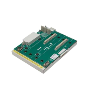
Product Introduction
The GE IS200ECTBG1A serves as the primary interface board for discrete signals within the Mark VIe turbine control architecture. It connects field devices like proximity probes, pressure switches, and solenoid valves directly to the VCMI or UCIO controllers.This board distinguishes itself through high-density channel packing and rigorous noise immunity testing. Field data indicates a mean time between failures (MTBF) exceeding 150,000 hours when operated within specified thermal limits. The optical isolation prevents ground loops from corrupting critical trip logic.
 Installation & Configuration Guide
 Installation & Configuration Guide
Preparation (10 min)
Gather a #2 Phillips screwdriver, anti-static wrist strap, and a multimeter. Verify the replacement board’s firmware revision matches the existing system (check the white sticker on the component side). Mismatched firmware can cause communication timeouts.
Removal (5–10 min)
Power down the control panel if possible. If hot-swapping, ensure the specific slot supports live removal (consult site SOPs). Disconnect the terminal block by loosening the two retaining screws. Pull the block straight out. Unseat the board by releasing the ejector levers at the top and bottom. Slide it out gently.
Installation (10 min)
Align the new IS200ECTBG1A with the backplane guides. Push firmly until the connector seats fully. Engage the ejector levers until they lock flush with the card edge. Reattach the terminal block. Tighten screws to 0.5 Nm torque—overtightening strips the plastic threads.
Power-On & Test (10 min)
Restore power. Watch the status LEDs. The “OK” LED should turn solid green within 15 seconds. A flashing red LED indicates a hardware fault or firmware mismatch. Use the ToolboxST software to force a test output on channel 1 and verify voltage at the terminal block.
Troubleshooting Quick Reference
| Symptom | Probable Cause | Action |
|---|---|---|
| Red LED Flashing | Firmware mismatch or bad backplane contact | Reseat board; check firmware version against project file. |
| No Input Response | Blown fuse or open circuit in field wiring | Measure 24V DC at terminal block; check field fuse. |
| Intermittent Signals | Loose terminal screw or vibration | Retorque all terminal screws; inspect for wire fatigue. |
| Communication Error | Dip switch setting incorrect | Verify dip switches match the schematic (usually all OFF). |
| Board Hot to Touch | Shorted output channel | Disconnect field wiring; measure resistance on outputs. |
Dimensions, Mounting & Wiring Notes
- Dimensions: 160 mm (H) × 100 mm (D) × 25 mm (W) approx.
- Mounting: Slides into standard Mark VIe 19-inch rack slots or mounts on DIN rail in standalone cabinets.
- Terminal Notes: Uses removable 3-row terminal blocks. Wire gauge must be 14–18 AWG stranded copper. Do not use solid core wire; it fractures under vibration.
- Warning: Ensure the shield drain wire connects to the chassis ground bar, not the signal common.
FAQ (5–7 questions)
Q: Can I swap an IS200ECTBG1A with an older ECTB model directly?
A: Physically, yes. Logically, no. The “G1A” revision often has updated gate arrays. You must update the controller’s configuration file in ToolboxST before swapping, or the system will flag a “Board Type Mismatch” error.Q: I see a faint burning smell after installation. Is this normal?
A: No. Immediately cut power. This usually indicates a reversed polarity connection on the 24V supply or a shorted field device. Check your wiring diagram again. New boards might smell slightly warm during the first burn-in, but never like burning plastic.Q: What is the lead time for a tested unit?
A: We hold stock of tested units. Orders placed before 2 PM EST ship same-day via FedEx Priority. Lead time is effectively 1–2 days for US domestic delivery.Q: Does this board support TMR (Triple Modular Redundant) applications?
A: Yes, but only when used in a set of three with specific cabling to three separate controllers. A single board operates in Simplex mode. For TMR, you need three identical boards and a TMR-rated backplane.Q: How do I verify the board isn’t a refurbished knock-off?
A: Check the holographic GE label on the edge. Look for the date code stamped on the PCB near the connector. Refurbished units often have mismatched date codes or signs of re-soldering on the pin headers. We provide a full test report with voltage readings for every channel.Q: My procurement team asks if this is “factory sealed.”
A: Most available stock is “New Surplus”—unused but removed from original packaging. It is functionally identical to factory sealed but lacks the outer shrink wrap. We test every unit to ensure it meets original specs.