
 Tel:
Tel:  Email:
  WhatsApp:
 Description
Key Technical Specifications
- Input Voltage: 24V DC nominal (Range: 18–32V DC) for internal logic & loop power
- Channel Count: 16 independent analog inputs
- Signal Types: 4-20mA, 0-20mA, 0-5V, 0-10V, ±10V, RTD (Pt100, Ni120)
- Input Impedance: 250Ω (current), >1MΩ (voltage)
- Resolution: 16-bit A/D conversion (handled by paired processor card)
- Isolation: 500V AC channel-to-channel and channel-to-ground
- Loop Power: Configurable 24V DC source per channel (fused)
- Operating Temperature: -30°C to +65°C (-22°F to +149°F)
- Storage Temperature: -40°C to +85°C
- Humidity: 5% to 95% non-condensing
- Connector Type: Euro-style pluggable terminal blocks (12-16 AWG)
- Diagnostic LEDs: Per-channel fault indication (open wire, over-range)
Product Introduction
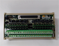
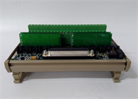
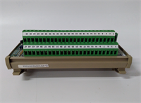
If you’ve ever chased a “drifting” temperature reading in a Mark VIe panel, the culprit was usually a cheap terminal strip or a corroded connection, not the controller itself. The GE IS200DTAIH1ACC fixes that by putting robust isolation and signal conditioning right at the entry point. I’ve installed these in everything from simple cycle peakers to combined heat and power units. They take the messy 4-20mA signals from pressure transmitters and the delicate resistance changes from RTDs, clean them up, and hand them off to the processor without adding noise.The “H1” revision is the standard for modern retrofits. It handles ground loops better than the old “D” series boards we used to see fail during monsoon seasons in outdoor cabinets. One specific thing I like: the per-channel fusing for the 24V loop power. In older designs, one shorted transmitter would blow a main fuse and kill all 16 channels. Here, you lose one channel, swap a tiny fuse, and the rest of the turbine monitoring stays online. Just watch out for the terminal block torque specs; these connectors are small, and overtightening strips the threads instantly.
Quality SOP & Tech Pitfalls (The Reality Check)
The Lab Report (SOP)
We treat analog boards differently than digital ones because accuracy matters. First, visual inspection under magnification to check for cold solder joints on the terminal blocks. Then, we mount the DTAI on a test rack with a precision calibrator (Fluke 754 or similar). We inject precise 4mA, 12mA, and 20mA signals into every single channel and verify the readback value against the expected 16-bit count. We also test the RTD simulation mode with a decade box to ensure linearization is correct. Finally, we check the isolation resistance between channels using a 250V DC Megger. If any channel leaks more than 1µA, it fails. We log the serial number and seal it in an ESD bag.
The Engineer’s Warning (Pitfalls)
The most common disaster I see? Mixing up 2-wire and 4-wire RTD wiring. The DTAI supports both, but the jumper settings inside the terminal block (or the wiring scheme) must match. If you wire a 3-wire RTD as a 2-wire without adjusting the compensation, your temperature reading will be off by 5-10 degrees, causing efficiency calculations to go haywire. Another nightmare: grounding the shield at both ends. This board has isolation for a reason. If you ground the cable shield at the sensor AND at this terminal board, you create a ground loop that induces 60Hz noise right into your analog signal. Always ground the shield at one end only—preferably at the cabinet entry, not on the board itself unless the schematic explicitly calls for it.
Installation & Configuration Guide
Time Estimate: 40 Minutes (Careful Wiring Required)
- Pre-Installation Safety ⚠️
- Isolate the 24V DC supply to the I/O rack.
- Critical: Take high-res photos of the existing wiring map. Note which channels are configured for Current (mA) vs. Voltage (V) vs. RTD.
- Verify the part number of the paired processor card (e.g., PAI or TAI) to ensure compatibility.
- Removal
- Label every wire ferrule. Analog wires often look identical; do not trust color alone.
- Unplug the terminal blocks from the board first, then release the DIN-rail clips. This prevents stress on the board traces.
- Slide the board out gently.
- Installation
- Verify Jumpers/Settings: Some DTAI revisions have small configuration jumpers for signal type selection. Match these exactly to the old board or the site electrical diagram.
- Seat the new IS200DTAIH1ACC firmly on the DIN rail/backplane.
- Re-insert the terminal blocks. Ensure they click into place. A half-seated block causes intermittent open-circuit faults.
- Torque terminals to 0.5 Nm. Use a calibrated screwdriver; don’t guess.
- Power-On & Testing
- Restore 24V DC power. Check the “Power” LED.
- Use a multimeter to verify 24V presence at the loop power terminals (if enabled).
- Inject a known 4mA signal into Channel 1. Verify the reading in ToolboxST matches within 0.1%.
- Repeat for a 20mA signal to check linearity. If the reading jumps or drifts, re-check your ground connections immediately.
IS200DTAIH1ACC GE
Compatible Replacement Models
- ✅ Drop-in Replacement: IS200DTAIH1ACD or IS200DTAIH1ACE.
- Note: Later suffix revisions. Identical form factor and electrical specs. These may have updated internal op-amps for better stability. Direct swap.
- ⚠️ Software Compatible: IS200DTAIG1ACC (Previous Revision).
- Warning: Physically fits, but earlier “G” versions might have slightly different noise filtering characteristics. Usually fine, but verify calibration data if high-precision measurements are critical.
- ❌ Hardware Mod Required: IS200DTAVH1ACC (Voltage Only Version).
- Advice: While it looks similar, this board lacks the current loop power circuitry. If you try to use it for 4-20mA transmitters, they won’t get power. Requires rewiring to external power supplies. Not recommended for direct replacement.
Frequently Asked Questions (FAQ)
Can I mix 4-20mA and RTD inputs on the same board?
Yes, that’s the whole point of the DTAI. Each channel is independently configurable. However, you must ensure the wiring and any internal jumpers (if applicable to your specific sub-revision) match the signal type for that specific channel. Don’t wire an RTD into a channel set up for voltage input, or you’ll get garbage data.My new board reads 0mA even though the transmitter is working. What’s wrong?
First, check if the 24V loop power fuse for that channel is blown. Second, verify the polarity; 4-20mA loops are polarized. If you swapped positive and negative, no current flows. Third, check the configuration in ToolboxST; if the software thinks the channel is disabled or set to “Voltage,” it won’t interpret the current correctly.Is this board hot-swappable?
In a TMR (Triple Modular Redundant) system, yes, you can usually swap one terminal board while the other two lanes keep running, provided you are careful not to short wires. In a Simplex system, swapping this board will interrupt the analog signals, likely triggering alarms or a trip depending on the logic. Always plan for a controlled bypass or shutdown if possible.What happens if I lose the terminal block plug?
Don’t try to jury-rig it with generic screws. Order a spare GE-specific plug (part number usually starts with IC200ACC…). Generic plugs often have different pitch or latch mechanisms that don’t seat fully, leading to vibration-induced failures later. Keep a few spares in your maintenance kit.Why is the price higher than generic analog modules?
Because this isn’t just a passive terminal strip. It includes isolation barriers, fusing, signal conditioning circuitry, and diagnostics designed specifically for the Mark VIe backplane communication. Generic modules lack the ruggedization for turbine environments and the specific diagnostic integration that tells you which channel failed before you even open the cabinet. In power generation, that specificity is worth the extra cost.


