 Tel:
Tel:  Email:
  WhatsApp:
 Description
Key Technical Specifications
- Input Type: Thermocouple (Types J, K, E, R, S, B, N, T)
- Channel Count: 16 Independent Differential Inputs
- Input Impedance: >10 MΩ per channel
- Resolution: 16-bit ADC (Effective)
- Accuracy: ±0.1% of reading ±1°C (at 25°C ambient)
- Cold Junction Compensation: Automatic per-channel CJC with ±0.5°C accuracy
- Common Mode Rejection: >100 dB at 50/60 Hz
- Operating Temperature: -30°C to +65°C (-22°F to +149°F)
- Power Consumption: Approx. 2.0 Watts @ 5V DC logic supply
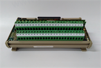
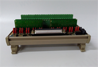
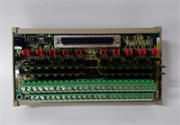
- Connector Type: 37-pin DIN backplane; Terminal block sold separately (TB37 series)
- Isolation: Channel-to-backplane isolation (250V AC continuous)
- Update Rate: Configurable (Typically 10ms to 100ms per channel scan)
Product Introduction
In a gas turbine, exhaust temperature spread is the difference between efficiency and a melted nozzle. The IS200DTAIH1ABB is the card watching those 16 thermocouples in the exhaust frame. I’ve seen generic analog cards drift by 5 degrees after a few heat cycles, causing the controller to falsely trip on “high spread.” This GE unit holds its calibration because the cold junction compensation (CJC) sensors are located right at the terminal entry point, not buried deep on the PCB where heat from other components skews the reading.Engineers specify this revision (‘B’) because it fixed a noise susceptibility issue in the original ‘A’ version when used near Variable Frequency Drives (VFDs). It filters out the high-frequency hash that used to make temperature readings jump around like a roulette wheel. The build quality is heavy-duty metal shielding around the analog front end. A word of caution: These cards are sensitive to ground loops. If your thermocouple sheaths are grounded at the turbine and you ground the shield at the cabinet, you’ll introduce error voltages that look like real temperature spikes. Isolate your shields correctly.
Quality SOP & Tech Pitfalls (The Reality Check)
The Lab Report (SOP)
Analog cards require precision testing, not just a “power on” check.
- Visual Inspection: Check the 37-pin connector for bent pins (common cause of open channels) and verify the terminal block interface area is clean.
- Precision Source Test: We use a Fluke 754 Documenting Process Calibrator to inject precise millivolt signals simulating Type K thermocouples at 0°C, 500°C, and 1000°C into all 16 channels simultaneously.
- CJC Verification: We manipulate the ambient temperature around the card in a thermal chamber while injecting a static signal to verify the Cold Junction Compensation tracks correctly. Error must be <0.5°C.
- Noise Immunity: We superimpose a 60Hz noise signal on the input to ensure the rejection ratio meets the >100 dB spec.
- Calibration Log: We record the offset and gain errors for each channel. If any channel deviates >0.15%, the card is rejected for critical turbine duty.
The Engineer’s Warning (Pitfalls)
Never ignore the terminal block type. The IS200DTAIH1ABB requires a specific terminal block (usually TB37x series) that matches its pinout and CJC sensor location. I once saw a technician force a generic terminal block onto the card. It fit mechanically, but the CJC sensor in the block wasn’t aligned with the card’s read point. The result? The controller read ambient temperature as 40°C higher than reality, causing a false startup abort. Always use the OEM or verified compatible terminal block.
Also, watch out for “open thermocouple” detection settings. If the diagnostic feature is enabled but the wiring has high resistance (corroded connections), the card might flag a “Sensor Open” fault even if the loop is technically closed. Clean your field connections before blaming the card.
Installation & Configuration Guide
Time estimate: 30 minutes (plus wiring time).
- Pre-Installation
- ⚠️ SHUTDOWN: While analog inputs can sometimes be swapped online in redundant systems, removing a temperature card during operation risks inducing noise spikes that could trip the turbine on “High Temp.” Schedule a maintenance window.
- Discharge static. Touch the chassis frame.
- Label Wires: Every single thermocouple wire (+ and -) must be labeled. Swapping polarity reverses the temperature reading (e.g., 500°C reads as -500°C).
- Removal
- Disconnect wires from the terminal block, not the card itself if possible. If the terminal block must come off, label every position.
- Release the DIN rail clip.
- Pull the card straight out of the 37-pin backplane connector.
- Installation
- Inspect Terminal Block: Ensure the CJC sensor area on the terminal block is clean and undamaged.
- Seat the new IS200DTAIH1ABB firmly onto the backplane. Listen for the click of the DIN rail lock.
- Re-connect wires strictly observing polarity (+ to +, – to -). Torque terminal screws to 0.5 Nm.
- Shielding: Connect cable shields to the ground bus bar at the cabinet entry, NOT at the terminal block (unless specifically directed by your grounding scheme to avoid ground loops).
- Power-On & Testing
- Restore power.
- LED Check: “OK” LED should be steady green. “Fault” LED off.
- Software Verify: Connect to the controller. Monitor the raw temperature values. They should match ambient temperature (if inputs are open) or field values within ±2°C.
- Simulate: If possible, apply a known heat source or calibrator to one channel to verify the reading updates correctly in the HMI.
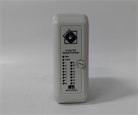
IS200DTAIH1ABB GE
Compatible Replacement Models
| Model Number | Compatibility Tier | Notes |
|---|---|---|
| IS200DTAIH1ABB | ✅ Drop-in Replacement | Exact match. Current standard for Type K/J thermocouple inputs. |
| IS200DTAIH1ABC | ✅ Drop-in Replacement | Newer revision. Improved filtering. Direct swap, no config changes needed. |
| IS200DTAIH1ABA | ⚠️ Software Compatible | Older revision. May require firmware patch to handle noise in VFD-heavy environments. Not recommended for new installs. |
| IS200DTCIH1Axx | ❌ Hardware Mod Required | Different input type (RTD). Pinout differs. Will damage thermocouples if connected. Do not use. |
Frequently Asked Questions (FAQ)
Can I mix different thermocouple types on this single card?
Technically, the hardware can accept different types, BUT the configuration in the controller software usually defines the type per channel or for the whole card depending on the firmware version. Mixing types on one card complicates the Cold Junction Compensation logic and increases the risk of configuration errors. Best practice: Dedicate one card to one thermocouple type (e.g., all Type K). If you must mix, verify your logic solver supports per-channel type definition.Why does the temperature reading drift when the cabinet heater turns on?
This points to a Cold Junction Compensation (CJC) issue. The CJC sensor measures the temperature at the terminal block to compensate for the reference junction. If the cabinet heater blows hot air directly onto the terminal block, the CJC reads high, and the calculated process temperature drops artificially. Ensure airflow in the cabinet is uniform and not directed straight at the analog cards.What do I do if one channel reads “Open Circuit” but the sensor is fine?
Check the continuity of the thermocouple extension wires first. Corrosion at the field connection is the #1 culprit. If the wire is good, check the terminal block screw tightness. A loose screw creates high resistance that the card interprets as an open. Finally, swap the wire to a known-good channel on the same card. If the fault moves with the wire, it’s the field wiring. If the fault stays on the channel, the card input circuitry is damaged.Is this card isolated from the backplane?
Yes, it provides channel-to-backplane isolation (250V AC). This protects the low-voltage controller logic from high-voltage transients if a thermocouple sheath shorts to a live component in the turbine. However, the channels are not isolated from each other. They share a common analog ground internally. Do not try to measure floating potentials between channels.How often should I recalibrate this module?
GE recommends verification every 1-2 years depending on the criticality of the application. In my experience, if the card passes the initial installation test and the environment is stable (no extreme thermal cycling of the cabinet itself), these units stay within spec for 5+ years. Don’t recalibrate just because the calendar says so; do it if you see unexplained drift in your temperature spreads.