 Tel:
Tel:  Email:
  WhatsApp:
 Description
Key Technical Specifications
| Parameter | Specification |
|---|---|
| Processor Speed | 200 MHz TMS320C67x DSP Core (Typical) |
| Control Loop Time | Configurable down to 0.5 ms (Fast analog loops) |
| Analog Input Channels | 32 Channels (High-speed, isolated) |
| Input Resolution | 16-bit Sigma-Delta ADC |
| Input Range | ±10V, 4-20mA (Software configurable per channel) |
| Communication | EGD (Ethernet Global Data) over Dual Redundant Fiber |
| Memory | 16 MB SDRAM, 4 MB Flash (for firmware/logic) |
| Operating Temp | -30°C to +65°C (Conformal coated for harsh env) |
| Connector Type | DC-37 Pin D-Sub (Field I/O), ST/BFOC (Fiber Comm) |
| Diagnostic LEDs | Run, Fault, Comm A/B, Watchdog, Status |
| Isolation Voltage | 2500 VAC RMS (Channel to Logic) |
| Mounting | Mark VIe Backplane Slot (VDRT/VME based) |
Product Introduction
When a gas turbine starts hunting on fuel pressure or vibrating oddly, nine times out of ten, the bottleneck isn’t the main CPU—it’s the DSP board struggling to keep up with the analog sampling rate. The GE IS200DSPXH1DBC is the muscle behind the Mark VIe system’s fast control loops. I’ve seen older ‘A’ revision boards choke on high-frequency noise in paper mill applications, but the ‘C’ revision (DBC) finally tightened up the filtering algorithms and hardware shielding.This board doesn’t just read sensors; it crunches the math for the fuel splitting logic and vibration monitoring in real-time, offloading the main UCP/UCC controller so the whole system doesn’t lag. The key metric here is the loop time: it handles sub-millisecond updates reliably, which is non-negotiable for DLN (Dry Low NOx) combustion control. One caveat: these boards are incredibly sensitive to grounding loops. If your cabinet ground isn’t under 1 ohm, you’ll see random spikes on the analog channels that look like sensor failures but are actually noise bleeding into the DSP. Fix your grounds first.
Quality SOP & Tech Pitfalls (The Reality Check)
The Lab Report (SOP)
We don’t trust “power-on self-tests” alone. Every IS200DSPXH1DBC gets loaded with a test harness that simulates all 32 analog channels simultaneously. We inject precise 1kHz sine waves and step changes to verify the ADC linearity and settling time. We check the DSP load percentage using the Toolbox diagnostic viewer; if it idles above 40% with no logic running, the board is suspect. We also perform a thermal cycle test (heating to 60°C) while running a continuous communication stress test on the fiber ports. Finally, we verify the firmware checksum against the official GE release notes for that specific revision.
The Engineer’s Warning (Pitfalls)
Firmware mismatch is the silent killer. You cannot just swap this board and expect it to work. The logic compiled in the Toolbox database is tied to specific firmware versions on the DSP. If the new board has an older firmware rev than the project expects, it will boot, show a “Comm Fault,” and refuse to execute the control block. I once lost a weekend commissioning slot because nobody checked the firmware version on the spare card until we tried to download the logic. Always check the version string in Toolbox before you pull the old card.Also, watch the fiber optic polarity. The TX/RX labels are tiny, and the connectors are often dusty. A reversed fiber link means the DSP talks to itself, not the master controller. If the “Comm B” LED is dark but “Comm A” is green, check your cross-over cables before assuming the port is dead. And for heaven’s sake, wear a wrist strap; static discharge kills these DSP chips instantly, and the damage often doesn’t show up until three months later during a hot summer day.
Installation & Configuration Guide
- Pre-Installation ⚠️
- Backup the current logic and configuration from the running controller to your laptop. Do not skip this.
- Verify the firmware version on the replacement board matches the project requirements (check the label or use a bench tester).
- Shut down the control power to the specific rack if possible, or prepare for a controlled bump if hot-swap is supported (rare for DSPs during critical ops).
- Removal
- Label all fiber optic cables (A and B networks) and the 37-pin analog cable.
- Disconnect fibers and cap them immediately. Dust is the enemy of optical signals.
- Release the retention clips and slide the board out gently. Do not force it; if it sticks, check for obstructions.
- Installation
- Verify Jumpers: Some site-specific configurations require specific jumper settings on the DSP header for termination or addressing. Compare with the old board photo.
- Seat the board firmly into the backplane until the locking clips engage.
- Reconnect the 37-pin analog cable, ensuring the screws are tight (loose shields cause noise).
- Connect fiber optics, ensuring a solid click. Do not bend the fibers tighter than a 1-inch radius.
- Power-On & Testing
- Apply power. Watch the LED sequence: Power -> Run (blinking) -> Run (solid).
- Connect via Toolbox and monitor the “Online” status. If it says “Fault,” read the error code immediately.
- Force a Logic Download: Even if the versions match, it is best practice to do a quick “Verify/Download” of the logic to ensure synchronization.
- Monitor the analog channel values in the diagnostic table. They should read stable zeros (or live process values) without wild spikes.
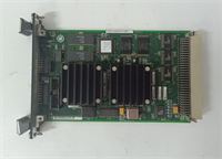
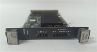
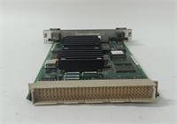
IS200DSPXH1DBC GE
Compatible Replacement Models
| Compatibility Tier | Model Number | Notes |
|---|---|---|
| ✅ Drop-in Replacement | IS200DSPXH1DBC | Exact match. Preferred for all current Mark VIe installations. |
| ⚠️ Software Compatible | IS200DSPXH1DBB | Previous revision. Hardware identical, but may require a firmware flash update via Toolbox before logic download. Estimate 30 mins extra labor. |
| ❌ Hardware Mod Required | IS200DSPXH1Axx | Older ‘A’ series boards have different memory maps and connector pinouts. Not compatible without significant backplane and logic re-engineering. |
Frequently Asked Questions (FAQ)
Can I hot-swap this DSP board while the turbine is running?
Technically, the Mark VIe backplane supports hot-swapping, but I strongly advise against it for the DSP module during operation. This board handles critical fast-control loops. Removing it might cause the master controller to trip on “Loss of Critical I/O” or default to a safe state, shutting down the machine. Only do this if the unit is already failed and you have full redundancy active (TMR configuration), and even then, proceed with extreme caution.The “Run” LED is blinking slowly. What does that mean?
A slow blink usually indicates the board is in “Bootloader” mode or waiting for a logic download. It hasn’t successfully started the user application. Check your fiber connections and ensure the master controller is sending the start command. If it persists, the firmware might be corrupted, requiring a re-flash via the service port.Do I need to recalibrate the analog inputs after swapping?
No. The calibration data is stored in the logic database and downloaded to the board, not permanently burned into the hardware (unless you used specific hardware trim pots, which are rare on these digital boards). Once the logic is downloaded, the scaling factors apply automatically. However, always verify a few key points against a handheld calibrator to be sure.Why is the board getting hotter than the others in the rack?
DSPs run hotter than standard I/O cards because they are doing heavy math. However, if it’s too hot to touch (>70°C case temp), check the cabinet cooling fans and airflow. Also, ensure the heat sink compound hasn’t dried out if this is a refurbished unit. Excessive heat shortens the life of the SDRAM significantly.Can I use this board in a Mark V system?
No. The Mark V and Mark VI architectures are completely different. The backplane pinout, communication protocol (IONET vs. EGD), and physical form factor are incompatible. Trying to force it will bend pins and destroy the backplane. Stick to the correct generation hardware.