 Tel:
Tel:  Email:
  WhatsApp:
 Description
Key Technical Specifications
| Parameter | Specification |
|---|---|
| Manufacturer | General Electric (GE) |
| Part Number | IS200BPVCG1BR1 |
| System Series | Speedtronic Mark VIe |
| Function | VME Bus Backplane Assembly |
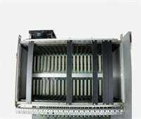
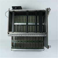
| Slot Count | 20 Slots (Mixed VCMI/UCIO/I/O compatibility) |
| Bus Standard | VME64x (64-bit data path) |
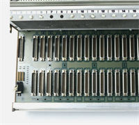
| Connector Type | DIN 41612 (2mm pitch, high-reliability gold plated) |
| Power Distribution | Integrated 24V DC and Ground buses |
| Current Rating | Typically 10A per rail (Verify total load calc) |
| Operating Temp | -30°C to +65°C (-22°F to +149°F) |
| Material | FR-4 High-Tg Laminate with impedance control |
| Mounting | Standard 19-inch Rack or Wall Mount Bracket |
| Revision | “R1” indicates specific grounding/power layout update |
Product Introduction
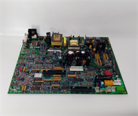
You can have the most expensive processors and the smartest logic code, but if your backplane is cracked or corroded, you have a very expensive paperweight. The IS200BPVCG1BR1 is the foundation of the Mark VIe system. It’s not a “smart” device; it’s a heavy-duty printed circuit board designed to survive decades of vibration, thermal cycling, and the occasional coolant leak. I’ve seen racks where the modules were pristine, but the backplane traces had micro-cracks from years of thermal expansion, causing intermittent “Ghost Trips” that drove maintenance crews crazy for months.The “R1” suffix on this model usually points to a revised power distribution layout that handles higher current loads better than the early versions, reducing voltage drop across the 20 slots. Engineers choose this specific part because it guarantees signal integrity for the VME64x bus, which is critical when three processors are voting on turbine speed in real-time. Don’t try to save money by buying a generic VME backplane; the pinout and keying are specific to GE’s safety architecture. If the keying doesn’t match, a module might seat physically but short out the 24V bus instantly.
Quality SOP & Tech Pitfalls (The Reality Check)
The Lab Report (SOP)
Backplanes are passive, but that doesn’t mean we skip testing. A bad trace here takes down the whole unit.
- Visual & Microscopic Inspection: We scan every inch of the PCB for hairline cracks, especially around the mounting holes and connector solder joints. We check the DIN connectors for bent pins or corrosion.
- Continuity Mapping: Using a specialized backplane tester (or a Fluke 87V with a custom harness), we verify continuity for every single pin on all 20 slots to the rear I/O connectors. One open circuit means scrap.
- Insulation Resistance: We megger the 24V power rails against the ground plane. It must read >100 MΩ. Any leakage suggests moisture ingress or carbon tracking.
- Impedance Spot Check: We sample critical high-speed data lines to ensure impedance hasn’t shifted due to delamination.
- Sealing: Wrapped in anti-static foam and boxed with rigid corner protectors. Bending this board during shipping is a fatal error.
The Engineer’s Warning (Pitfalls)
The biggest disaster I’ve witnessed involved a “near miss” installation. A tech forced a module into a slot where the plastic keying didn’t quite line up. He used a screwdriver to pry it in. He bent a single 24V pin inside the DIN connector, which touched the ground pin. When he powered up, he didn’t just blow a fuse; he arc-welded the backplane trace, destroying the entire $15,000 assembly. Never force a module. If it doesn’t slide in smoothly, check the keying.Another silent killer is oxidation on the unused slots. If you have empty slots in your rack, leave the filler panels installed. I’ve pulled backplanes from coastal plants where salt air crept into open slots, corroding the connector pins. When they finally tried to add an I/O module two years later, the new card couldn’t make contact, causing sporadic communication failures that took days to diagnose. Keep those fillers on.
Installation & Configuration Guide
Time Estimate: 60-90 Minutes (Heavy lifting and precision required)
- Pre-Installation ⚠️
- CRITICAL: Power down the entire control cabinet. Disconnect ALL external power sources (24V DC, 120V AC). Wait 10 minutes.
- Label every single wire connected to the rear terminal blocks or front connectors. Take panoramic photos of the wiring before touching anything.
- Remove all modules from the old backplane first. Do not try to lift the backplane with modules still seated; the weight will snap the connectors.
- Removal
- Disconnect all ribbon cables and rear wiring harnesses.
- Unscrew the mounting brackets holding the backplane to the rack/chassis.
- Carefully slide the backplane out. Watch out for sharp edges on the rack frame. These boards are heavy and awkward; get a second pair of hands.
- Installation
- Compare the new IS200BPVCG1BR1 side-by-side with the old one. Verify slot count and connector positions match exactly.
- Mount the new backplane securely. Torque the mounting screws to spec. A loose backplane vibrates, leading to cracked solder joints over time.
- Module Insertion: Re-install modules one by one. Ensure the ejector levers are open before insertion. Slide in until it stops, then close the levers to lock it. Do not use excessive force.
- Power-On & Testing
- Reconnect all wiring based on your labels and photos. Double-check polarity on the 24V DC input.
- Before turning on the main power, use a multimeter to check for shorts between 24V and Ground at the input terminals.
- Power up. Verify 24V DC is present at the backplane input.
- Check module LEDs. They should boot in sequence. If a specific slot fails to power, re-seat the module and check the backplane pin continuity for that slot.
IS200BPVCG1BR1 GE
Compatible Replacement Models
| Compatibility Tier | Model Number | Notes |
|---|---|---|
| ✅ Drop-in Replacement | IS200BPVCG1BR1 | Exact match. Guaranteed fit and pinout compatibility. |
| ⚠️ Software Compatible | IS200BPVCG1B | Older revision. Physical fit is identical, but power distribution might differ slightly. Verify current ratings before loading high-power modules. |
| ❌ Hardware Mod Required | IS200BPVCH1A | Different slot count (e.g., 12-slot vs 20-slot) or different bus standard (VME32 vs VME64x). Requires rewiring and chassis modification. Not recommended. |
Frequently Asked Questions (FAQ)
Can I replace just one damaged slot on the backplane?
No. The backplane is a multi-layer PCB with buried traces. You cannot repair a single slot reliably in the field. If a slot is damaged (bent pins, burnt traces), you must replace the entire backplane assembly. Trying to solder individual pins usually damages the internal layers.My system works fine, but I see corrosion on slot 15. Should I replace it now?
Yes. If you see corrosion, the contact resistance is already high. It might work today, but the next time the plant heats up or vibrates, that connection will fail, causing a random trip. Replace the backplane during the next scheduled outage. It’s cheaper than an unscheduled shutdown.Is the IS200BPVCG1BR1 compatible with Mark V modules?
No. Mark V and Mark VIe use completely different form factors and bus architectures. The connectors won’t align, and the voltage levels differ. Do not attempt to mix generations.How do I know if my backplane is the cause of intermittent faults?
If you have random communication errors across multiple modules, or if modules in a specific area of the rack keep failing, suspect the backplane. Perform a wiggle test (carefully) on seated modules while monitoring diagnostics. If the fault appears when you apply slight pressure, the backplane connectors are likely worn or cracked.Does this backplane come with mounting hardware?
Usually, no. The “BR1” part number typically refers to the bare board assembly. You often need to reuse the mounting brackets, standoffs, and screws from your existing chassis. Check the vendor description carefully; if you need a full kit, ask for the “Chassis Assembly” rather than just the backplane.