 Tel:
Tel:  Email:
  WhatsApp:
 Description
Key Technical Specifications
- Port Count: 8 x 10/100 Base-TX RJ45 ports (Auto-MDIX supported)
- Switching Capacity: 1.6 Gbps non-blocking backplane
- Packet Buffer: 1 MB shared memory buffer per port
- Latency: < 10 microseconds store-and-forward latency
- Network Protocols: TCP/IP, UDP, IGMP v2 (Snooping), IEEE 802.1Q (VLAN tagging)
- Redundancy: Supports Rapid Spanning Tree Protocol (RSTP) for loop prevention
- Input Voltage: 24V DC nominal (Range: 18–32V DC), dual input terminals for redundancy
- Power Consumption: Approx. 4.5 Watts typical (varies with port load)
- Isolation: 1500V RMS isolation per port (protects against ground loops)
- LED Indicators: Link/Activity (Green/Amber), Speed (10/100), Power OK, Fault
- Environmental Rating: Conformal coated (Class G1/G2) for harsh industrial atmospheres
- Mounting: Integrated into Mark VIe 21-slot or 12-slot chassis backplane
Product Introduction
If your Mark VIe system relies on an external switch sitting in a hot, dusty cabinet, you’re asking for trouble. The GE IS200AEPCH1BAA brings the network switch inside the controller chassis, cutting out the extra cabling and external power supplies that usually fail first. I’ve seen entire turbine controls go dark because a cheap commercial switch overheated in July; this board is built to sit right next to the CPU, handling the same heat and vibration without blinking. It’s not just a hub; it’s a managed switch that understands GE’s IONet traffic priorities, ensuring critical trip signals never get stuck behind bulk data logs.The “H1” revision with the “BAA” suffix is the current standard for reliable network segmentation within the rack. Earlier versions sometimes struggled with broadcast storms during firmware downloads, but GE tightened the buffer management here. You get true IGMP snooping, which stops multicast traffic from flooding every port and choking the CPU. A word of caution: these boards are incredibly sensitive to IP address conflicts and duplicate MAC addresses. I once spent three days chasing a “ghost” network failure only to find a technician had plugged a laptop directly into a spare port with a static IP that matched the controller. Treat this board like the brain of your network, because it is.
Quality SOP & Tech Pitfalls (The Reality Check)
The Lab Report (SOP)
We don’t trust “plug and play” with network hearts. Every IS200AEPCH1BAA gets a visual inspection for damaged RJ45 pins—common from rough shipping. Then, we mount it in a live Mark VIe test chassis and flood all 8 ports with simultaneous traffic using an Ixia network tester to verify zero packet loss at 100% load. We test RSTP failover by physically cutting one uplink cable and measuring the re-convergence time (must be < 50ms). We also verify IGMP snooping is active by sending multicast streams and ensuring they only go to subscribed ports. Finally, we log the MAC address and firmware version, then seal it in ESD-safe packaging. We use a Fluke LinkRunner to certify port health before shipping.The Engineer’s Warning (Pitfalls)
The silent killer of these boards is ground loops. Because the AEPC connects directly to the backplane and field Ethernet cables, any potential difference between the chassis ground and the remote device ground can drive current through the signal shields, frying the internal transformers. I saw a plant in Texas lose three AEPC boards in a week because their instrument ground was floating 15V above earth ground. The other major pitfall is ignoring the port configuration. By default, some ports might be disabled or set to specific VLANs in the factory config. If you plug a critical I/O pack into a disabled port, you’ll stare at a dark LED wondering why the rack is dead. Always check the switch configuration in ToolboxST before assuming the hardware is bad.
Installation & Configuration Guide
Phase 1: Pre-Installation
⚠️ SHUT DOWN NETWORK POWER. Disconnect 24V DC to the chassis. Wait 15 seconds for capacitors to discharge.
⚠️ DOCUMENT CABLE ROUTING. Photograph the existing Ethernet cable connections (Port 1 to Port 8). Note which ports connect to CPUs, I/O packs, and HMIs. Label every cable clearly.Phase 2: Removal
Gently unclip the RJ45 connectors; do not pull on the cable itself. Release the chassis locking screws or DIN rail clips. Slide the AEPC module straight out. Avoid touching the gold backplane pins. If the board sticks, check for a hidden retention tab; never force it.Phase 3: Installation
VERIFY PORT MAP. Before seating the new IS200AEPCH1BAA, review your photos to ensure you know which physical port maps to which logical device. Seat the module firmly until the locking mechanism clicks. Reconnect Ethernet cables to the exact same ports. Ensure cables are dressed away from high-voltage wiring to prevent EMI interference.Phase 4: Power-On & Testing
Restore 24V DC power. Watch the LED sequence: “PWR” should be solid green. “Link” LEDs should illuminate for connected devices. The “Activity” LEDs should flash rhythmically. Open ToolboxST and navigate to the Network View; verify all nodes (CPUs, I/O packs) appear online with no “Communication Loss” alarms. Perform a ping test from the HMI to each node to confirm latency is under 5ms.
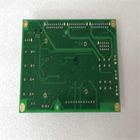
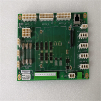
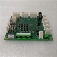
IS200AEPCH1BAA GE
Compatible Replacement Models
- ✅ Drop-in Replacement: IS200AEPCH1AAA – The base version of the H1 revision. The “BAA” suffix typically denotes a minor component update (e.g., different transformer vendor). Functionally identical in 99% of cases. Verify firmware compatibility.
- ⚠️ Software Compatible: IS200AEPCG1AAA – Previous generation (G1). Hardware is similar, but may lack the latest buffer management features or require a firmware downgrade. Expect 15 mins for software verification and potential project tweaks.
- ❌ Hardware Mod Required: IS200TCIOH1A – This is a Terminal Board, not a switch. It physically fits some slots but serves a completely different purpose. Do not attempt to use as a substitute.
Frequently Asked Questions (FAQ)
Can I replace this board while the turbine is running?
No. The AEPC is the central nervous system for the entire chassis. Removing it cuts communication to all I/O packs and processors in that rack. Even in a redundant TMR system, losing the switch in one rack can cause a “mismatch” vote and trigger a shutdown. Plan for a controlled outage.Why are some of my port LEDs dark even though devices are plugged in?
First, check the cable integrity with a tester. Second, verify the device on the other end is powered and transmitting. Third, and most likely, the port might be administratively disabled in the switch configuration. Access the switch settings via ToolboxST and ensure all required ports are enabled and set to “Auto-Negotiate.”Is this switch compatible with standard office Ethernet devices?
Yes, physically. You can plug a laptop or standard switch into any port. However, the Mark VIe network uses specific IP subnets and often relies on IGMP snooping for multicast traffic. Plugging in an unconfigured office switch can create a loop or flood the network with broadcast traffic, crashing the control system. Only connect authorized engineering laptops with static IPs assigned by the site network admin.What does the “BAA” suffix mean compared to “AAA”?
GE uses suffixes like “BAA” to indicate minor manufacturing changes, such as a different supplier for the Ethernet magnetics or a thicker conformal coating. It does not typically change the form, fit, or function. It is generally backward compatible. However, always cross-reference the part number with your GE Project Properties file to ensure no known incompatibilities exist for your specific firmware version.How do I reset the switch to factory defaults?
There is no physical “reset” button on the AEPC board. Resetting requires connecting via the service port (if accessible) or using ToolboxST to reload the default switch configuration file from the project database. Be careful: doing this live will wipe your custom VLAN and port settings, potentially taking the unit offline. Only perform this during a maintenance window with a backup config ready.