 Tel:
Tel:  Email:
  WhatsApp:
 Description
Key Technical Specifications
| Parameter | Specification |
|---|---|
| Manufacturer | General Electric (GE) |
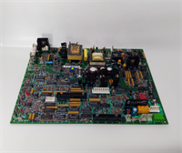
| Primary Part Number | IS200IQAGH1A (Standard Mark VIe Quadrature Module) |
| System Series | Speedtronic Mark VIe |
| Function | Quadrature Speed & Phase Input |
| Input Channels | 4 Independent Quadrature Inputs (Channel A/B) |
| Signal Type | Differential or Single-ended (Configurable) |
| Voltage Range | 5V to 24V DC logic levels (Schmitt Trigger) |
| Max Frequency | Typically up to 20 kHz – 50 kHz (dependent on firmware) |
| Resolution | High-resolution timestamping for precise RPM calculation |
| Input Voltage | 24 VDC nominal (via backplane) |
| Operating Temp | -30°C to +65°C (-22°F to +149°F) |
| Mounting | Mark VIe Backplane (VDIM slot) |
| Firmware | Version specific to speed measurement algorithms |
Product Introduction
If your turbine control system can’t tell exactly how fast the shaft is spinning or which way it’s turning, you’re flying blind. The IP-QUADRATURE functionality, housed in the IS200IQAGH1A module, is the eyes of the Speedtronic Mark VIe for rotational dynamics. Unlike simple frequency inputs that just count pulses, this board reads two offset signals (Channel A and Channel B) to determine direction instantly. This is critical for preventing reverse rotation damage during startup and for precise phasing during synchronization.I’ve seen plants try to use standard digital input cards for speed sensing, and it always ends in tears. The jitter on a standard card is too high for tight speed control loops. The IQA board uses dedicated hardware counters and timestamping logic to get microsecond-level accuracy. Whether you’re monitoring a heavy-frame gas turbine or a high-speed steam unit, this board handles the noisy environment of a proximity probe signal without false triggering. The “Quadrature” capability means it can also detect a broken wire or a failed probe instantly by monitoring the phase relationship between A and B, triggering a “Sensor Fail” before the speed reading goes wild.
Quality SOP & Tech Pitfalls (The Reality Check)
The Lab Report (SOP)
Speed cards demand precision testing; a 1% error here can mean a 30 RPM deviation at full speed.
- Visual Inspection: Check the input terminal blocks for heat discoloration and the fiber optic isolators (if equipped on specific revisions) for clarity.
- Signal Simulation: We use a high-precision function generator to simulate quadrature signals (A leads B, then B leads A) at various frequencies (1 Hz to 10 kHz).
- Direction Verification: We verify the board correctly identifies “Forward” vs. “Reverse” rotation in the diagnostic software within 2 cycles of the input signal.
- Noise Immunity Test: We inject common-mode noise onto the input lines to ensure the Schmitt triggers don’t false-trigger. The board must ignore spikes under 2V.
- Sealing: Anti-static packaging. These high-speed input circuits are sensitive to ESD.
The Engineer’s Warning (Pitfalls)
The most common headache with these boards is wiring polarity and shielding. Quadrature signals rely on the precise timing edge of Channel A relative to Channel B. If you swap A and B wires, the turbine thinks it’s spinning backward and will trip immediately. If you don’t use twisted pair shielded cable, electromagnetic interference (EMI) from nearby VFDs can induce false edges, causing the speed reading to jump erratically. I once saw a turbine hunt ±50 RPM because the tech used unshielded lamp cord for the probe extension.Another trap is the voltage threshold configuration. Some older proximity probes output 8V peaks, while newer ones might be 24V. The IQA module has jumpers or software config for voltage thresholds. If set wrong, the board might miss pulses at low speed (during rolling) or clip the signal at high speed. Always verify the probe spec sheet against the module configuration before energizing.
Installation & Configuration Guide
Time Estimate: 45 Minutes
- Pre-Installation ⚠️
- Secure the turbine in a “Rolling” or “Shutdown” state. Do not install while at full speed unless you have redundant probes and understand the risk of transient trips.
- Identify the specific probe pairs (e.g., 1X, 2X speed probes) and label cables clearly as “Channel A” and “Channel B”.
- Verify the replacement module is IS200IQAGH1A (or the specific revision matching your system).
- Removal
- Disconnect the probe cables from the terminal block.
- Release the retention clip and slide the module out.
- Inspect the old module’s terminals for corrosion or loose screws.
- Installation
- Insert the new IS200IQAGH1A into the slot. Ensure firm seating.
- Reconnect cables. CRITICAL: Double-check A/B pairing. A mismatch here causes reverse rotation faults.
- Tighten terminal screws to torque spec. Loose connections cause intermittent signal loss.
- Verify jumper settings (if applicable) for voltage levels match the probe type.
- Power-On & Testing
- Power up the control system.
- Use the engineering toolbox to monitor the raw input status. Rotate the shaft slowly (barring gear).
- Verify the software shows “Forward” rotation and the RPM count increases smoothly.
- Check for “Sensor Fail” alarms. If present, re-check wiring continuity and shield grounding.
IP-QUADRATURE GE
Compatible Replacement Models
| Compatibility Tier | Model Number | Notes |
|---|---|---|
| ✅ Drop-in Replacement | IS200IQAGH1A | Standard Mark VIe Quadrature Input Module. Exact functional match for “IP-QUADRATURE”. |
| ⚠️ Software Compatible | IS200IQAGH1B | Newer revision. May require firmware update in the toolbox to recognize new hardware features. |
| ❌ Hardware Mod Required | IS200TCAGH1A | This is a Thermocouple module. Physically fits but functionally useless for speed. Do not confuse slot assignments. |
Frequently Asked Questions (FAQ)
What does “Quadrature” actually mean in this context?
It means the module reads two signals (A and B) that are 90 degrees out of phase. By seeing which signal leads the other, the controller knows the direction of rotation. It also allows for x4 resolution counting (counting rising and falling edges of both channels), giving much smoother speed data at low RPMs.Can I use this module for simple frequency inputs (single channel)?
Yes, the IQA module can typically be configured to accept single-channel frequency inputs if you don’t need direction detection, but it’s overkill. You would usually reserve these expensive slots for critical speed/phase measurements where direction matters.My speed reading is erratic/jumping. Is the board bad?
Usually not. 90% of erratic speed readings are due to bad cabling, poor shielding, or a failing proximity probe, not the IQA board itself. Check your cable shields (grounded at one end only) and verify the probe gap voltage. Only suspect the board if the issue persists after swapping cables and probes.Is this module redundant?
The Mark VIe system achieves redundancy by using multiple IQA modules in different racks (TMR configuration) voting on the speed signal. The module itself is single-channel processing, but the system architecture makes it redundant. You typically need three of these for a TMR speed input.Does “IP-QUADRATURE” refer to a specific legacy part?
“IP-QUADRATURE” is often a functional name used in older documentation or by technicians to describe the function performed by the IS200IQAGH1A. If you are ordering a spare, always order by the specific part number IS200IQAGH1A (or your system’s specific revision) to ensure compatibility.