 Tel:
Tel:  Email:
  WhatsApp:
 Description
Key Technical Specifications
| Parameter | Specification |
|---|---|
| Processor Speed | 1.8 GHz Intel Pentium M |
| User Memory | 256 MB (RAM) |
| I/O Capacity | Up to 128,000 discrete points |
| Communication Ports | 2x Ethernet (10/100 Mbps), 1x Serial (RS232/485) |
| Backplane Bus | Reflective Memory (Genius compatible via bridge) |
| Program Scan Time | < 1 ms for typical logic blocks |
| Operating Temp | 0°C to 60°C (32°F to 140°F) |
| Power Requirement | 5V DC @ 3.5A (typical backplane load) |
| Physical Size | Single slot width (HP) in RX7i rack |
| Firmware Support | Proficy Machine Edition v8.0 or later recommended |
| Battery Backup | Lithium battery for RAM retention (field replaceable) |
| Certifications | UL, cUL, CE, TUV |
Product Introduction
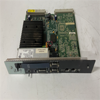
The GE IC698CPE020-CC serves as the central brain for the PACSystems RX7i architecture, handling high-speed logic execution and complex motion coordination. Engineers deploy this unit in large-scale manufacturing lines where deterministic control over thousands of I/O points is non-negotiable.Unlike earlier RX7i CPUs, the IC698CPE020-CC doubles the user memory to 256 MB and increases clock speed to 1.8 GHz, reducing scan times by approximately 40% in heavy math applications. It maintains backward compatibility with existing RX7i I/O modules but requires specific firmware levels to avoid handshake errors during hot swaps.
Installation & Configuration Guide
Phase 1: Preparation (10 min)
Verify the rack power is OFF and locked out (LOTO). Check the backplane slot assignment; this CPU must occupy Slot 1 in standard configurations. Inspect the module pins for bending—a common issue if previous installers forced the card. Have a static wrist strap ready; the exposed processor heatsink is ESD sensitive.Phase 2: Removal (5–10 min)
If replacing an existing unit, disconnect Ethernet cables first. Note the DIP switch settings on the old unit (take a photo—always). Loosen the captive screws at the top and bottom of the faceplate. Pull the module straight out using the ejector handles. Do not wiggle excessively; this damages the backplane connector keys.Phase 3: Installation (10 min)
Align the new IC698CPE020-CC with the slot guides. Ensure the DIP switches match your network configuration (usually all OFF for default Ethernet IP assignment via software). Push firmly until the backplane connector seats fully—you should feel a distinct “click.” Tighten the captive screws to 4.5 in-lbs. Reconnect communication cables.Phase 4: Power-On & Test (10 min)
Restore rack power. Observe the LED sequence: PWR (Green), OK (Flashing Green then Solid), and RUN (Off initially). If the OK LED flashes red/green, a firmware mismatch exists. Connect via Proficy Machine Edition. Perform a “Verify” operation to check logic integrity against the offline project file. Force a test output to confirm I/O mapping.
Troubleshooting Quick Reference
| Symptom | Probability | Action |
|---|---|---|
| OK LED Flashing Red/Green | High | Firmware version mismatch. Update CPU firmware using Proficy Machine Edition before downloading logic. |
| No Communication via Ethernet | Medium | Check DIP switch position 1. If ON, it forces a static IP defined in hardware config. Verify subnet mask matches PC. |
| RAM Battery Low Alarm | Medium | Replace CR2032 battery immediately while powered. Logic loss occurs within minutes if power cycles without backup. |
| Module Not Detected in Rack | Low | Reseat the module. Inspect backplane pins for debris or corrosion. Try a different slot if redundant setup allows. |
| Excessive Scan Time (>50ms) | Low | Review logic for unoptimized loops or excessive floating-point math. Use task profiling tools in the IDE. |
Dimensions, Mounting & Wiring Notes
- Dimensions: 1.60″ W × 6.50″ H × 5.90″ D (Single Horizontal Slot)
- Mounting Method: Slides into RX7i universal backplane; secured by two captive front-panel screws. No DIN rail direct mount (requires chassis).
- Terminal Notes:
- Ethernet Ports: RJ45 connectors located on the front faceplate. Use Cat5e or better shielded cable for industrial noise immunity.
- Serial Port: DB9 connector. Pinout follows standard RS232 DTE configuration.
- Battery Compartment: Located behind the small access door on the front. Polarity is critical; reverse installation destroys the holder.
IC698CPE020-CC GE
FAQ
Q: Can I use the IC698CPE020-CC to replace my old IC698CPE010?
Yes, it is a direct form-fit replacement. However, you must upgrade your Proficy Machine Edition software to support the newer instruction set and increased memory capacity. The logic usually transfers without modification, but compile it again to ensure optimization.Q: What exactly does the “-CC” suffix mean in the model number?
It indicates the conformal coating option. This protects the internal PCB from humidity, salt spray, and corrosive gases. It’s essential for wastewater treatment plants or coastal facilities. Don’t scrape the coating off to read chip numbers; you’ll void the protection.Q: I bought this used; how do I know the battery isn’t dead?
Check the “BAT” LED on the front panel. If it’s lit red, the battery is critically low. Even if it’s off, assume the battery is weak if the unit has been in storage for over a year. Replace it proactively before putting the controller into service.Q: Is this unit compatible with Genius I/O blocks?
Indirectly, yes. The CPU itself doesn’t talk Genius directly. You need a Genius Bus Controller module (like IC697BEM731) in the same rack to bridge the communication. The CPE020 handles the logic, while the bridge module handles the physical protocol.Q: Why is the lead time so long for “new” units?
GE (Emerson) discontinued this series years ago. Any vendor claiming “Factory New” stock is likely selling old surplus that has sat on a shelf. We classify ours as “New Surplus” or “Refurbished” to be transparent. Always ask for the manufacture date code if freshness matters for your warranty.