
 Tel:
Tel:  Email:
  WhatsApp:
 Description
Key Technical Specifications
| Parameter | Value |
|---|---|
| Processor Speed | 450 MHz |
| User Memory | 256 MB (RAM) |
| Flash Storage | 1 GB (Non-volatile) |
| Serial Ports | 2 (RS-232/RS-485 selectable) |
| Ethernet Port | 10/100 Mbps (SRTP, Modbus TCP/IP) |
| USB Port | 1 (Type B, programming only) |
| Backplane Bus | PCI-based high-speed bus |
| Battery Backup | Lithium, 3-year typical life |
| Operating Temp | 0°C to 60°C (32°F to 140°F) |
| Power Consumption | 2.5 A @ 5V DC (backplane) |
| Dimensions (HxWxD) | 12.7 x 3.5 x 9.5 cm (approx.) |
| Weight | 0.45 kg (1.0 lb) |
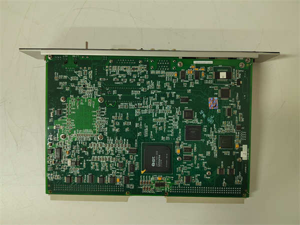
Product Introduction
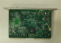
The IC698CPE020 serves as the central brain for GE Fanuc’s PACSystems RX7i architecture, handling high-speed logic execution and complex motion coordination. Engineers deploy this unit in large-scale manufacturing lines where deterministic control and massive I/O counts are non-negotiable requirements.Unlike lower-tier controllers, this module executes 10,000+ Boolean instructions per millisecond, ensuring tight synchronization across distributed racks. Its 1 GB flash memory stores extensive historical data logs without needing external cards, reducing cabinet footprint. (We often see users max out the Ethernet bandwidth before hitting CPU limits in vision-guided applications.)
Installation & Configuration Guide
Phase 1: Preparation (10 min)
- Verify rack power is OFF. Measure backplane voltage; ensure 5V DC is present and stable.
- Check slot allocation. The CPE020 must occupy Slot 1 (leftmost) in the primary rack.
- Gather tools: #2 Phillips screwdriver, anti-static wrist strap, laptop with Machine Edition software.
- Inspect connector pins on the module rear. Bent pins cause immediate communication failure.
Phase 2: Removal (5–10 min)
- Disconnect all field wiring from terminal blocks if attached directly (rare for CPU, usually separate I/O).
- Unplug Ethernet and serial cables. Note port assignments with tape if multiple networks exist.
- Loosen the two captive mounting screws at the top and bottom of the faceplate.
- Pull the module straight out. Do not rock it side-to-side; this damages the backplane connector.
- Real-world detail: If you smell burnt ozone upon removal, inspect the backplane socket for carbon tracking before inserting a replacement.
Phase 3: Installation (10 min)
- Align the module guides with the rack rails. Slide in firmly until the backplane connector seats fully.
- You should feel a distinct “click” or solid stop. No gaps should remain between the module face and rack.
- Tighten mounting screws to 1.2 Nm torque. Overtightening strips the plastic threads.
- Reconnect communication cables. Ensure the Ethernet clip locks audibly.
Phase 4: Power-On & Test (10 min)
- Apply rack power. Watch the LED sequence: PWR (Green), RUN (Off initially), BAT (Green if good).
- The OK LED will flash amber during POST (Power-On Self-Test). This takes ~15 seconds.
- Solid Green OK indicates successful boot. Flashing Red means firmware mismatch or hardware fault.
- Connect via USB or Ethernet. Verify online status in Proficy Machine Edition.
- Force a logic scan. Monitor cycle time; it should stabilize under 10ms for standard logic.
IC698CPE020 GE
Troubleshooting Quick Reference
| Symptom | Probability | Fastest Check | Action |
|---|---|---|---|
| OK LED Flashing Red | High | Firmware Version | Compare installed firmware vs. project definition. Reload if mismatched. |
| No PWR LED | Medium | Backplane Voltage | Measure 5V DC at adjacent slot. Check rack power supply fuse. |
| COMM LED Off | High | Cable/Port | Swap Ethernet cable. Try USB port for local connection. |
| BAT LED Red | Low | Battery Voltage | Replace CR2032 battery immediately. Download program to retain data. |
| Random Faults | Medium | Heat/Ventilation | Touch heatsink. If >60°C, clean dust filters or add cabinet fan. |
| I/O Timeout Errors | High | Bus Configuration | Verify rack fill settings in hardware config match physical layout. |
Dimensions, Mounting & Wiring Notes
- Dimensions: 127 mm (H) x 35 mm (W) x 95 mm (D).
- Mounting: Horizontal DIN rail or vertical rack mount. Vertical mounting requires derating ambient temp by 10°C.
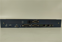
- Terminal Notes: The CPU uses proprietary backplane connectors for I/O data. External wiring applies only to serial ports (DB9) and Ethernet (RJ45).
- Grounding: Connect the rack grounding lug to earth ground using 14 AWG wire minimum. Floating grounds induce communication noise.
- Clearance: Maintain 50 mm clearance above and below for airflow. The processor runs hot under full load.
FAQ
Q: Can I use the IC698CPE020 in an RX3i rack?
A: No. The physical backplane connectors and bus protocols differ entirely between RX7i and RX3i series. Attempting insertion will damage pins.Q: I bought this used; how do I know the firmware isn’t corrupted?
A: We run a 24-hour load test simulating max I/O traffic. However, you should always verify the checksum against your original project file before going live. (Better safe than sorry.)Q: What happens if the battery dies while power is off?
A: You lose retentive memory (V-memory, timers, counters). The logic program stays in Flash, but runtime data vanishes. Replace the battery within 30 days of the low-battery alarm.Q: Is this compatible with newer Emerson PACSystems controllers?
A: Partially. Logic migration usually requires code updates due to instruction set changes. Consult the Emerson migration guide for specific function block replacements.Q: Why is the lead time longer than standard stock items?
A: Since GE discontinued the RX7i line, we source from verified surplus stocks and perform full refurbishment. Each unit undergoes individual testing, adding 2-3 days to shipping.Q: Does it support Modbus TCP out of the box?
A: Yes, the Ethernet port supports SRTP and Modbus TCP/IP natively. No additional daughter cards are needed for basic SCADA integration.


