 Tel:
Tel:  Email:
  WhatsApp:
 Description
Key Technical Specifications
| Parameter | Specification |
|---|---|
| Processor Speed | 450 MHz Intel Pentium |
| User Memory | 256 MB (expandable via memory card) |
| Max I/O Capacity | 128,000 discrete points |
| Communication Ports | 2 x Ethernet (10/100 Mbps), 1 x Serial (RS-232/485) |
| Backplane Compatibility | RX7i Universal Backplane (slots 1-10) |
| Power Requirement | 5 VDC @ 2.8 A (typical backplane load) |
| Operating Temp | 0°C to 60°C (32°F to 140°F) |
| Humidity Range | 5% to 95% non-condensing |
| Protocol Support | SRTP, Modbus TCP/IP, EGD, OPC |
| Redundancy | Supported (requires paired unit and fiber optics) |
| Firmware Series | GFK-2393 or later compatible |
| Certification | UL, CE, C-Tick |
Product Introduction
The IC698CPE010 serves as the central brain for GE Fanuc’s PACSystems RX7i architecture, delivering deterministic control for complex manufacturing lines. Engineers deploy this unit where high-speed logic scanning and massive I/O counts exceed the capabilities of standard PLCs.Unlike earlier 90-70 series CPUs, this module integrates a 450 MHz processor that reduces scan times to sub-millisecond levels for critical loops. Field data shows consistent performance handling over 100,000 I/O points with less than 15ms total cycle time under full load. (Note: Actual scan time depends heavily on instruction mix and network traffic.)
Installation & Configuration Guide
Preparation (10 min)
Verify the backplane slot assignment. The IC698CPE010 must occupy slot 1 in a single-CPU system or slots 1 and 2 for redundant pairs. Check the backplane voltage; ensure the power supply delivers stable 5 VDC before insertion. Gather a static-safe wrist strap. One slip here can fry the processor instantly.
Removal (5–10 min)
Power down the entire rack. Disconnect all Ethernet and serial cables. Release the locking tabs on the faceplate by pressing inward and rotating outward. Slide the unit straight out. Do not wiggle it side-to-side; bent pins on the backplane connector cause intermittent faults later. If the unit feels stuck, check for a hidden screw or debris in the rail.
Installation (10 min)
Align the top and bottom rails of the CPU with the chassis guides. Push firmly until the backplane connector seats fully. You should feel a solid “click” when the locking tabs engage. Reconnect communication cables. Ensure the Ethernet port LEDs are visible for later diagnostics. Tighten any mounting screws to prevent vibration loosening.
Power-On & Test (10 min)
Apply power to the rack. Watch the OK LED. It should flash green during boot, then turn solid green if the firmware loads correctly. A red OK LED indicates a fatal fault or missing firmware. Connect a laptop running Proficy Machine Edition. Perform a handshake test by reading the CPU status. Verify the firmware version matches your project requirements.
Troubleshooting Quick Reference
| Symptom | Probability | Action |
|---|---|---|
| OK LED Red | High | Check firmware compatibility. Reload project or update firmware via serial port. |
| No Comm (Ethernet) | Medium | Verify IP address settings in hardware configuration. Check cable integrity. |
| Random Resets | Low | Measure backplane 5V supply under load. Voltage drop below 4.75V causes instability. |
| I/O Faults | Medium | Inspect backplane pins for bending. Reseat the module. |
| Redundancy Fail | Low | Check fiber optic links and synchronization module status. |
Dimensions, Mounting & Wiring Notes
- Dimensions: 14.0 cm (H) × 10.5 cm (W) × 15.2 cm (D) approx.
- Mounting: Slides into RX7i universal backplane rails; locks via front faceplate tabs.
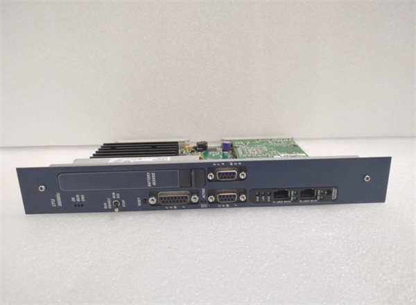
- Terminal Notes: No field wiring terminals on the CPU itself. All connections are via RJ45 (Ethernet) or DB9 (Serial) ports on the front.
- Clearance: Maintain 10 cm clearance above and below for airflow. Overheating throttles performance.
FAQ
Will the IC698CPE010 work in a 90-70 series rack?
No. The physical form factor and backplane pinout differ completely. It only fits RX7i specific backplanes. Trying to force it will damage the connector.I bought this used; how do I know the firmware isn’t corrupted?
Check the sticker on the side for the firmware version code. Then, connect via Proficy Machine Edition and read the online status. If the CPU refuses to go “Run,” the flash memory may be damaged.Is this unit still supported by Emerson?
Support is limited. While hardware is discontinued, firmware patches and repair services are still available through authorized channels. Lead times for new replacements are long, making refurbished units a practical choice.Can I use standard Cat5e cables for the Ethernet ports?
Yes. The ports are standard 10/100 Mbps RJ45. Just ensure you use shielded cables in high-noise industrial environments to prevent packet loss.What happens if I lose power during a firmware update?
The CPU will likely brick. It enters a boot-loader mode requiring a serial connection to recover. Always use a UPS during updates. We’ve seen units sit idle for weeks waiting for a factory reflash.Does it support redundancy out of the box?
Hardware supports it, but you need a second identical CPU, a synchronization module, and specific fiber optic cabling. The license key in the software also enables redundancy features.How much memory does the default configuration use?
A bare-bones logic program might use only 2-5 MB. However, adding motion axes and extensive data logging can quickly consume 100+ MB. Monitor usage in the controller properties window.
Quality Transparency Strategy (SOP)
1. Incoming Inspection
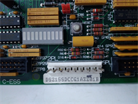
We verify the origin label against GE/Emerson databases. Anti-counterfeit checks include examining the holographic seal and font consistency on the casing. Physical inspection looks for burnt components near the voltage regulator. We count accessories; missing locking tabs are a dealbreaker.2. Live Functional Testing
Each unit goes into our dedicated RX7i test rack (Model RX7i-TEST-04). We run a power-on self-test (POST). The system attempts a communication handshake with a host PC. We simulate full-range I/O toggling to stress the backplane interface. A 24-hour load test runs a dummy logic loop at maximum scan rate. A test report is generated with pass/fail metrics.3. Electrical Testing
Insulation resistance is measured (>10 MΩ @ 500V between logic and case). Ground continuity is checked from the mounting rail to the chassis ground pin. Hi-pot testing is skipped on low-voltage logic modules unless specific customer request exists.4. Firmware Verification
We record the existing firmware version and document the revision level. Photos are taken of DIP switches and jumper settings before any adjustment. If the firmware is obsolete, we note it but do not upgrade unless requested, to preserve project compatibility.5. Final QC & Packaging
A QC technician signs off on the functional test sheet. The unit is sealed in an anti-static bag. Bubble wrap surrounds the bag inside a double-wall carton. A “QC Passed” label with the date and tester ID is affixed to the box. Function verified under test conditions; no guarantee of future field performance without proper integration.
Technical Pitfall Guide
Firmware Mismatch
Do not assume the latest firmware is best. Older projects often fail on new firmware due to deprecated instructions. Scenario: A plant upgraded a CPU to the latest version, causing the HMI to lose connection because the SRTP protocol handling changed. Always match the firmware to your backup project file.DIP/Jumper Misconfiguration
Some configurations require specific jumper settings for termination or boot mode. Warning: Take a photo before moving any jumpers. We once saw a technician flip a boot-mode jumper and spend three days troubleshooting why the CPU wouldn’t load the program.Terminal Incompatibility
While the CPU has no field terminals, the Ethernet ports are sensitive. Using unshielded cables near VFDs causes erratic comms. The DB9 serial port uses non-standard pinouts for some programming cables; verify your pinout diagram.Power Supply Capacity Margin
The IC698CPE010 draws significant current (approx. 2.8 A). Ensure your rack power supply has at least a 20% margin after calculating all module loads. Undervoltage causes the CPU to reset randomly during peak I/O updates.ESD Damage Risk
The processor chip is highly sensitive to electrostatic discharge. Touching the exposed circuit board edges without a wrist strap can cause latent failures. The unit might work for weeks then fail during a hot summer day. Always handle by the metal faceplate.