 Tel:
Tel:  Email:
  WhatsApp:
 Description
Key Technical Specifications
| Parameter | Specification |
|---|---|
| Memory Capacity | 16 MB (Reflective Memory) |
| Data Transfer Rate | Up to 1 Gbps (fiber optic dependent) |
| Latency | < 1 microsecond (node-to-node) |
| Network Topology | Ring or Star (via external media converters) |
| Connector Type | 2x LC Fiber Optic ports (multimode) |
| Supported CPUs | IC698CPE010, CPE020, CPE030, CPE040 |
| Max Nodes per Ring | 8 (standard), up to 255 with repeaters |
| Operating Temp | 0°C to 60°C (32°F to 140°F) |
| Power Consumption | 1.2A @ 5V DC (typical backplane load) |
| Update Mechanism | Hardware-based automatic replication (no CPU overhead) |
| Physical Size | Single slot width (HP) in RX7i rack |
| Certifications | UL, cUL, CE |
Product Introduction
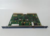
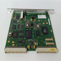
The GE IC698CMX016 acts as a dedicated coprocessor for the PACSystems RX7i, enabling deterministic data sharing across multiple controllers without burdening the main CPU scan cycle. It is critical in applications like synchronized motion control lines or distributed safety systems where microseconds matter.This module distinguishes itself by using hardware-level reflective memory rather than standard Ethernet messaging, achieving sub-microsecond update rates between nodes. While the IC698CPE020 CPU handles logic, the CMX016 manages the data mirror, ensuring that a change in one controller appears instantly in all others connected to the ring.
Installation & Configuration Guide
Phase 1: Preparation (10 min)
Ensure the entire rack system is powered down and locked out. Verify you have the correct fiber optic patch cables (LC-LC, multimode 62.5/125µm is standard). Inspect the fiber ports on the module for dust caps; remove them only when ready to plug in. Dirty connectors are the #1 cause of link failures—use a fiber inspection microscope if available.Phase 2: Removal (5–10 min)
If replacing a failed unit, carefully disconnect the fiber cables first. Note the “In” and “Out” port orientation relative to the network ring direction. Take a photo of the existing module’s position and any jumpers (though this model typically has none). Loosen the captive screws and slide the module out using the ejectors. Avoid bending the fiber cables sharply; they break internally easily.Phase 3: Installation (10 min)
Insert the IC698CMX016 into an available slot adjacent to the CPU (preferred for bus speed, though not strictly required). Slide it in until the backplane connector seats firmly. Tighten screws to 4.5 in-lbs. Connect the fiber optic cables: ensure the transmit (TX) of one node connects to the receive (RX) of the next. You should hear a faint “click” when the LC connector locks.Phase 4: Power-On & Test (10 min)
Power up the rack. Watch the LED indicators: PWR (Green), LINK (Green on both ports if ring is closed), and ACT (Flashing during data transfer). If LINK is off, check fiber polarity or clean the connectors. In Proficy Machine Edition, navigate to the Hardware Configuration. Verify the module is recognized and the memory map is allocated correctly. Run a “Force” test on a shared memory bit from a different node to confirm replication.
Troubleshooting Quick Reference
| Symptom | Probability | Action |
|---|---|---|
| LINK LED Off (One or Both) | High | Fiber cable fault or dirty connector. Clean ends with alcohol wipe and inspect. Check for broken fibers (bend radius violation). |
| ACT LED Never Flashes | Medium | No data traffic configured. Verify the CPU logic is actually reading/writing to the reflective memory addresses. |
| CPU Faults on Boot | Medium | Slot configuration mismatch. Ensure the Hardware Configuration in software matches the physical slot location of the CMX016. |
| Intermittent Data Loss | Low | EMI interference or bad SFP (if using copper converters). Ensure fiber cables are routed away from VFD power lines. |
| Ring Broken Alarm | Low | One node in the network is down or powered off. The ring requires all nodes to be active for full redundancy unless configured as a star. |
Dimensions, Mounting & Wiring Notes
- Dimensions: 1.60″ W × 6.50″ H × 5.90″ D (Single Horizontal Slot)
- Mounting Method: Slides into RX7i universal backplane; secured by two captive front-panel screws.
- Terminal Notes:
- Fiber Ports: Two LC duplex connectors on the faceplate. Do not look directly into the ports while powered (Class 1 Laser).
- Cable Type: Multimode fiber (62.5/125µm or 50/125µm). Max segment length depends on cable quality (typically up to 2km).
- Handling: Fiber cables must maintain a minimum bend radius of 1.5 inches. Sharp kinks permanently attenuate the signal.
IC698CMX016 GE
FAQ
Q: Does the IC698CMX016 work with the newer Emerson PACSystems RSTi?
No. This module is strictly for the RX7i chassis architecture. The RSTi platform uses entirely different communication modules and form factors. Trying to force compatibility will result in physical damage to the backplane.Q: How many of these modules can I put in one rack?
Technically, you can fill every slot, but practically, you usually only need one per CPU to establish the network link. The limit is defined by the total backplane current capacity and the number of nodes supported in the reflective memory ring (max 8 standard nodes).Q: My LINK light is green, but data isn’t updating. What gives?
A green LINK light only means the physical layer (fiber) is intact. It doesn’t guarantee the software configuration is correct. Check your Proficy project: did you assign the correct global memory addresses? Did you download the hardware config to the CPU after adding the module?Q: Can I mix fiber types (single-mode vs. multimode)?
No. The IC698CMX016 ports are optimized for multimode fiber. Using single-mode fiber will result in very poor coupling efficiency or no link at all due to core size mismatch. Stick to OM1 or OM2 multimode patch cords.Q: I’m seeing “Reflective Memory Timeout” errors. Is the card dead?
Not necessarily. This often happens if one node in the ring is powered down or resetting, breaking the token passing loop. Check the status of all other controllers in the network. If all are running, then yes, the specific module’s transceiver might be failing.