 Tel:
Tel:  Email:
  WhatsApp:
 Description
Key Technical Specifications
| Parameter | Specification |
|---|---|
| Input Voltage | 48V DC (Nominal), Range: 36V – 72V DC |
| Total Power Output | 100 Watts |
| 5V DC Output | 12.0 Amps (Max) |
| 24V DC Output | 1.5 Amps (Max) |
| Input Current | ~2.5A @ 48V DC (full load) |
| Efficiency | > 85% typical |
| Backplane Compatibility | Series 90-70 Universal Backplane (any slot) |
| Operating Temp | 0°C to 60°C (32°F to 140°F) |
| Storage Temp | -40°C to 85°C (-40°F to 185°F) |
| Protection | Over-voltage, Over-current, Thermal shutdown |
| Isolation | 500V DC input-to-output isolation |
| MTBF | > 100,000 hours (calculated) |
| Physical Size | Single slot width (HP) in Series 90-70 rack |
| Certifications | UL, cUL, CE |
Product Introduction
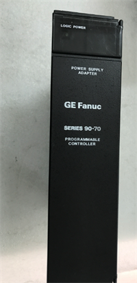
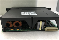
The GE IC697PWR724 is a high-capacity power supply designed specifically for the Series 90-70 PLC architecture, accepting a wide-range 48V DC industrial input. It delivers stable 5V DC logic power to the backplane and 24V DC for field devices, supporting racks with heavy I/O density or communication modules.Distinguished from lower-wattage models like the PWR720, the IC697PWR724 provides up to 12A on the 5V rail, allowing engineers to populate full racks with high-current CPUs and specialty modules without voltage droop. Its switching design maintains regulation even during input dips down to 36V DC, preventing nuisance trips in unstable power environments.
Installation & Configuration Guide
Phase 1: Preparation (10 min)
Lock out all power sources to the 48V DC bus. Verify the incoming voltage with a multimeter; it must be between 36V and 72V DC. Connecting 24V DC will cause a “Undervoltage” fault, while exceeding 72V may destroy the input capacitors. Inspect the terminal block screws for stripping. Ensure the rack has adequate ventilation; this unit dissipates ~15W of heat at full load.Phase 2: Removal (5–10 min)
Disconnect the 48V DC wiring from the front terminal block. Label wires clearly (+48V, -48V, Frame Ground). Loosen the captive mounting screws at the top and bottom of the module faceplate. Use the ejector handles to pull the module straight out. Do not twist the module; this can damage the backplane power pins.Phase 3: Installation (10 min)
Slide the new IC697PWR724 into any available slot in the Series 90-70 rack (power distribution is parallel across the backplane). Push firmly until seated. Tighten captive screws to 4.5 in-lbs. Reconnect wiring: ensure polarity is correct. Reverse polarity triggers immediate protection shutdown but can stress internal diodes. Torque terminal screws to 5–7 in-lbs. A loose screw here causes arcing and burnt terminals—a common field failure.Phase 4: Power-On & Test (10 min)
Remove LOTO and energize the 48V DC source. Observe the front LEDs: PWR (Green) should illuminate immediately. The OK LED will flash then go solid green if internal self-tests pass. Measure the 5V and 24V outputs at the terminal block; they should read 5.0V ±2% and 24.0V ±5%. If the PWR LED is off, check input fuse and polarity. If OK flashes red, the backplane load may exceed 100W.
Troubleshooting Quick Reference
| Symptom | Probability | Action |
|---|---|---|
| PWR LED Off | High | No input voltage or reversed polarity. Measure 48V DC at terminals. Check external fuse/breaker. |
| OK LED Flashing Red | Medium | Overload condition. Calculate total backplane current draw. Remove non-essential modules to test. |
| 24V Output Low (<22V) | Medium | Excessive load on 24V rail. This supply only provides 1.5A @ 24V. Use external 24V supply for field devices if needed. |
| Module Hot to Touch | Low | Ambient temperature >60°C or failing fan in enclosure. Check airflow. Thermal shutdown occurs at ~85°C internal. |
| Intermittent Reset | Low | Input voltage dipping below 36V DC during motor starts. Add bulk capacitance to the 48V bus or check source capacity. |
Dimensions, Mounting & Wiring Notes
- Dimensions: 1.60″ W × 6.50″ H × 5.90″ D (Single Horizontal Slot)
- Mounting Method: Slides into Series 90-70 universal backplane; secured by two captive front-panel screws.
- Terminal Notes:
- Input: Screw terminals for +48V DC, -48V DC (Return), and Chassis Ground. Wire gauge: 14–22 AWG.
- Output: Internal distribution via backplane. No external output terminals for 5V.
- 24V Aux: Some configurations allow tapping 24V from specific pins, but primary use is internal. Verify pinout in hardware manual before wiring external loads.
- Torque: Critical. Loose power terminals cause heat buildup and melting plastic. Retorque after 24h of operation if possible.
IC697PWR724 GE
FAQ
Q: Can I use the IC697PWR724 in a Series 90-30 rack?
No. The physical form factor and backplane pinout are different. The Series 90-30 uses smaller PS series modules (e.g., IC693PWR321). Forcing this module into a 90-30 rack will bend pins and likely short the backplane.Q: My system needs 20A @ 5V. Will two PWR724 modules work together?
No, you cannot parallel these power supplies for increased current. The Series 90-70 backplane draws from whichever supply is active or distributes load based on internal impedance, but they do not actively share load balancing. You would need to split the I/O across two separate racks, each with its own power supply.Q: What happens if I accidentally connect 24V DC instead of 48V DC?
The unit will not turn on. The undervoltage lockout circuit prevents operation below ~30V. It generally won’t damage the supply, but the PLC will not run. Double-check your facility power labeling before connecting.Q: Is the 24V output enough to power my sensors?
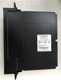
Unlikely for a full rack. The IC697PWR724 only provides 1.5A @ 24V, intended mostly for powering communication modules or a few low-current sensors. Best practice is to use an external 24V DC power supply for the majority of field instrumentation and wire them separately.Q: How do I know if the unit is refurbished or new surplus?
Check the date code on the serial number label. If the date is >10 years old, it is surplus stock. If the label looks fresh or has a “Tested” sticker from a third party, it is refurbished. We always disclose this status in the product condition field. Never assume “New” means factory sealed for discontinued items.