
 Tel:
Tel:  Email:
  WhatsApp:
 Description
Key Technical Specifications
| Parameter | Specification |
|---|---|
| Input Voltage | 85–264 VAC (47–63 Hz) or 100–300 VDC |
| Total Output Current | 35 Amps (combined 5V and 24V rails) |
| 5 VDC Output | Adjustable 4.75–5.25 VDC, max 20A |
| 24 VDC Output | Fixed 24 VDC, max 15A (derated if 5V > 20A) |
| Mounting Style | Slides into 90-70 series rack slot |
| Cooling | Convection (no internal fan) |
| Operating Temp | 0°C to 60°C (32°F to 140°F) |
| Hold-up Time | 16ms minimum at full load |
| Efficiency | >85% typical |
| Protection | Over-voltage, over-current, thermal shutdown |
| Indicator LEDs | OK (Green), Fault (Red) |
| Weight | Approx. 2.1 kg (4.6 lbs) |
Product Introduction
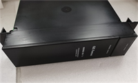
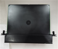
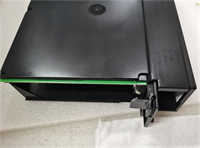
The IC697PWR710H is a high-current power supply designed specifically for large-scale GE Fanuc 90-70 series PLC racks. It converts standard AC or DC line voltage into the precise 5 VDC and 24 VDC required by CPU and I/O modules.This “H” revision unit delivers up to 35 amps of combined current, supporting racks with heavy analog or communication module loads. Field measurements indicate stable voltage regulation even when input line voltage drops to 85 VAC. (Note: The 24V output is often used to power external sensors, reducing the need for separate power supplies.)
Installation & Configuration Guide
Preparation (10 min)
Calculate the total current draw of all modules in the rack. Ensure the sum does not exceed 35A. Verify the input voltage source matches the unit’s rating (check the label on the side). Turn off the main breaker. Lock out/tag out the panel. One mistake here causes arc flash.
Removal (5–10 min)
Disconnect AC input wiring from the terminal block. Loosen the mounting screws securing the unit to the rack frame. Slide the power supply straight out. It is heavy; support it with one hand to prevent dropping it on lower cards. Inspect the backplane connector pins for bending.
Installation (10 min)
Align the new IC697PWR710H with the rack guides. Push firmly until the backplane connector seats. You will feel resistance before the final click. Tighten the mounting screws securely. Reconnect AC input wires to the correct terminals (L, N, Ground). Torque terminals to 0.5–0.6 Nm. Loose wires cause heat buildup.
Power-On & Test (10 min)
Remove lockout tags. Energize the main breaker. Observe the front LED immediately. A solid green “OK” light confirms proper operation. A red “Fault” light indicates an internal error or overload. Use a multimeter to measure the 5V output at the test points. Adjust the trim pot if voltage reads outside 4.9–5.1 VDC.
Troubleshooting Quick Reference
| Symptom | Probability | Action |
|---|---|---|
| No LEDs Lit | High | Check incoming AC voltage. Verify fuse integrity (internal or external). |
| Red Fault LED | Medium | Disconnect load modules one by one to isolate a short circuit. |
| 5V Output Low (<4.75V) | Medium | Measure total rack load. Reduce I/O count or upgrade to dual PSUs. |
| Intermittent Resets | Low | Check terminal screw tightness. Vibration loosens connections over time. |
| Burning Smell | Critical | Cut power immediately. Replace unit. Do not attempt repair. |
Dimensions, Mounting & Wiring Notes
- Dimensions: 14.0 cm (H) × 10.5 cm (W) × 16.5 cm (D) approx.
- Mounting: Occupies one slot in 90-70 series rack; secured via front screws and rear rail.
- Terminal Notes: Input terminals accept up to 12 AWG wire. Output is via backplane; no field wiring terminals for DC output.
- Clearance: Allow 5 cm clearance above for heat dissipation. Although fanless, it runs hot under full load.
IC697PWR710H GE
FAQ
Can I use this power supply in a 90-30 series rack?
No. The physical dimensions and backplane connectors are incompatible. The 90-70 series units are larger and heavier. Forcing it will break the plastic guides.I see a red light after installation. What should I check first?
Check your wiring. Did you swap Line and Neutral? Is the ground connected? If wiring is correct, the rack load might exceed 35A. Remove some I/O modules and try again.Is the “H” revision better than the “G” or “F”?
Generally, yes. Later revisions often include updated component tolerances and improved thermal handling. However, functionally they are identical for most applications. Stick to what your spare parts list specifies.How do I adjust the 5V output voltage?
Locate the small trim potentiometer on the front faceplate near the LEDs. Use a non-conductive screwdriver. Turn clockwise to increase, counter-clockwise to decrease. Measure while adjusting. Don’t force it past the stops.What happens if I lose AC power briefly?
The unit has a 16ms hold-up time. If the outage is shorter than that, the PLC keeps running. Longer outages cause a shutdown. You might need a UPS for critical processes. We’ve seen lines stop because of a 20ms blip.Can I stack two of these in one rack?
No. The 90-70 rack design supports only one primary power supply per base unit. For redundancy, you need a specific redundant power system configuration with diodes, not just two standard units.Does this unit generate a lot of heat?
Yes, especially at high loads. It relies on convection cooling. Ensure your enclosure has adequate ventilation fans. Touching the case after 4 hours of operation can burn your hand.
Quality Transparency Strategy (SOP)
1. Incoming Inspection
We verify the serial number against GE manufacturing records. Anti-counterfeit checks focus on the casing mold quality and label print resolution. Physical inspection looks for scorched terminal blocks or swollen capacitors. We verify the presence of the adjustment potentiometer cap.2. Live Functional Testing
Each unit is mounted in a dedicated 90-70 test rack. We apply 120 VAC and 240 VAC inputs sequentially. Power-on self-test verifies LED sequences. We connect an electronic load bank to simulate 20A on the 5V rail and 10A on the 24V rail. A 4-hour load test ensures thermal stability. A test report logs voltage ripple and regulation accuracy.3. Electrical Testing
Insulation resistance is tested (>10 MΩ @ 500V between input and chassis). Ground continuity is verified from the ground screw to the chassis. Hi-pot testing is performed at 1500 VAC for 1 minute to ensure isolation integrity.4. Firmware Verification
Not applicable (hardware-only device). We document the hardware revision level (“H”) and take photos of the internal board layout if the case is opened for cleaning. DIP switches are rare on this model; we verify jumper settings for voltage selection if present (usually auto-ranging).5. Final QC & Packaging
A QC technician signs the load test report. The unit is wrapped in anti-static foam. Heavy-duty bubble wrap protects the terminals. A “QC Passed” label with voltage test data is attached. Function verified under test conditions; field performance depends on proper rack integration.
Technical Pitfall Guide
Firmware Mismatch
Not applicable for power supplies, but configuration errors occur. Users sometimes forget to set the input voltage jumper if the unit is not auto-ranging (rare for this model, but check the label). Assuming auto-range without verifying can destroy the unit on 240V lines.DIP/Jumper Misconfiguration
Some older revisions have manual voltage selection jumpers. Warning: Take a photo before touching anything. Setting a 120V jumper to a 240V source causes immediate catastrophic failure. Smoke appears within seconds.Terminal Incompatibility
Using solid core wire instead of stranded wire can lead to loose connections under vibration. The terminal blocks are designed for stranded wire with ferrules. Solid wire works initially but loosens as the metal relaxes.Power Supply Capacity Margin
Engineers often miscalculate the 24V load. The 35A rating is a combined limit. If you pull 20A for 5V logic, you cannot pull 15A for 24V sensors. The curve derates. Always leave a 20% margin. Running at 100% load shortens capacitor life drastically.ESD Damage Risk
While less sensitive than CPUs, the control board inside can be damaged by ESD. Static discharge can affect the voltage regulation circuitry, causing drift over time. Wear a wrist strap when handling the exposed board during cleaning.


