 Tel:
Tel:  Email:
  WhatsApp:
 Description
Key Technical Specifications
| Parameter | Value |
|---|---|
| Total Power | 75 Watts |
| Output 1 (Logic) | 5V DC @ 10.0 A |
| Output 2 (Field) | 24V DC @ 1.0 A |
| Input Voltage | 85–264 VAC or 90–300 VDC |
| Input Frequency | 47–63 Hz |
| Inrush Current | 30 A max (at 264 VAC) |
| Hold-up Time | 16 ms minimum (at full load) |
| Efficiency | >75% typical |
| Operating Temp | 0°C to 60°C (32°F to 140°F) |
| Storage Temp | -40°C to 85°C |
| Humidity | 5% to 95% (non-condensing) |
| Dimensions (HxWxD) | 12.7 x 5.1 x 15.2 cm (approx.) |
Product Introduction
The IC697PWR710F provides stable 5V and 24V DC power to GE 90-70 series PLC racks, ensuring reliable operation of CPUs and high-density I/O modules. Facilities rely on this unit to maintain logic integrity during minor grid fluctuations thanks to its 16ms hold-up capability.
This specific “F” revision features improved thermal management compared to earlier versions, allowing continuous operation at 60°C ambient without derating. It delivers a steady 10 amps on the 5V rail, critical for driving large backplane loads. (Technicians often note the fan runs quieter on the F-revision than on the older C or D models.)
Installation & Configuration Guide
Phase 1: Preparation (10 min)
- Disconnect main AC power to the control panel. Lockout/Tagout (LOTO) is mandatory.
- Verify input voltage selector switch (if present on chassis) matches supply voltage. Most PWR710F units are auto-ranging.
- Inspect the backplane connector pins on the power supply. Look for bent pins or oxidation.
- Ensure the rack mounting slot (usually far right or left depending on config) is empty and clean.
Phase 2: Removal (5–10 min)
- Remove terminal block wiring from the front face. Label wires clearly: L, N, FG, +5V, +24V, Com.
- Loosen the two captive screws securing the module to the rack.
- Pull the module straight out. Support the weight; it is heavier than standard I/O cards.
- Real-world detail: If the unit feels excessively hot to the touch immediately after power down, check the rack cooling fans before installing the replacement.
Phase 3: Installation (10 min)
- Align the module with the rack guides. Slide it in firmly until the backplane connector seats.
- You must feel solid resistance when fully seated. Do not force it if it binds; check alignment.
- Tighten mounting screws to 1.2 Nm. Loose mounting causes vibration damage to the backplane pins.
- Reconnect wiring. Use ring terminals for AC inputs to prevent strand fraying.
- Torque terminal screws to 0.5 Nm. Loose connections cause arcing and heat buildup.
Phase 4: Power-On & Test (10 min)
- Remove LOTO devices and apply AC power.
- Observe the front LEDs: PWR (Green) should illuminate immediately. OK/FAULT LED behavior varies by firmware.
- Measure output voltages at the terminal block with a multimeter.
- Target 5V DC: 4.95V – 5.05V.
- Target 24V DC: 23.5V – 24.5V.
- Listen for abnormal coil whine or fan grinding. A high-pitched squeal indicates failing capacitors.
- Verify CPU boots. If the CPU flashes red, re-check the 5V rail under load.
Troubleshooting Quick Reference
| Symptom | Probability | Fastest Check | Action |
|---|---|---|---|
| No PWR LED | High | Input Fuse/Breaker | Check AC input voltage at terminals. Verify panel breaker is closed. |
| 5V Output Low (<4.75V) | High | Overload Condition | Disconnect I/O modules one by one. Check for shorted backplane traces. |
| Fault LED Red | Medium | Over-Temp | Feel the heatsink. Clean dust from rack filters. Verify ambient temp <60°C. |
| Intermittent Resets | Medium | Loose Connection | Retorque terminal screws. Check backplane seating of the power module. |
| 24V Missing | Low | Internal Fuse | The 24V rail has a separate internal protection. May require factory repair. |
| Fan Noise | Low | Bearing Wear | Replace fan assembly if accessible, or swap the entire power supply unit. |
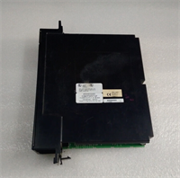
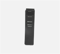
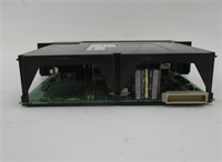
IC697PWR710F GE
Dimensions, Mounting & Wiring Notes
- Dimensions: 127 mm (H) x 51 mm (W) x 152 mm (D).
- Mounting: Inserts directly into the 90-70 series rack backplane. Secured by two front-face screws.
- Terminal Notes: AC inputs accept 12–22 AWG wire. DC outputs accept 12–20 AWG. Use copper conductors only.
- Grounding: Connect the Frame Ground (FG) terminal to the cabinet earth ground with 14 AWG wire. This is critical for noise immunity.
- Clearance: Do not block the ventilation slots on the top and bottom. Maintain 75 mm vertical clearance for airflow.
FAQ
Q: Will the IC697PWR710F work in a 90-30 series rack?
A: No. The physical form factor and backplane pinout are completely different. It fits only 90-70 series racks.
A: No. The physical form factor and backplane pinout are completely different. It fits only 90-70 series racks.
Q: My 5V reading is 4.8V; is that acceptable?
A: Barely. GE specs allow ±5% (4.75V–5.25V), but running at the lower limit risks CPU instability under load. We recommend checking for excessive voltage drop in your wiring or an overloaded backplane.
A: Barely. GE specs allow ±5% (4.75V–5.25V), but running at the lower limit risks CPU instability under load. We recommend checking for excessive voltage drop in your wiring or an overloaded backplane.
Q: Can I use this to power external 24V sensors?
A: Technically yes, but don’t. The 1A limit on the 24V rail is intended for limited field use. Use a dedicated DIN-rail power supply for sensors to avoid starving the PLC logic.
A: Technically yes, but don’t. The 1A limit on the 24V rail is intended for limited field use. Use a dedicated DIN-rail power supply for sensors to avoid starving the PLC logic.
Q: What does the “F” in the model number mean?
A: It indicates the hardware revision. Revision F includes updated components for better reliability and thermal performance compared to revisions A through E. Always match or exceed the revision specified in your system design.
A: It indicates the hardware revision. Revision F includes updated components for better reliability and thermal performance compared to revisions A through E. Always match or exceed the revision specified in your system design.
Q: How long does the refurbishment testing take?
A: Each unit undergoes a 24-hour burn-in test at 80% load. We simulate voltage sags to verify the hold-up time meets the 16ms spec. (We reject about 15% of incoming cores that fail this specific test.)
A: Each unit undergoes a 24-hour burn-in test at 80% load. We simulate voltage sags to verify the hold-up time meets the 16ms spec. (We reject about 15% of incoming cores that fail this specific test.)
Q: Is there a battery backup on this power supply?
A: No. The IC697PWR710F does not contain a battery. Logic retention is handled by a battery on the CPU module itself, not the power supply.
A: No. The IC697PWR710F does not contain a battery. Logic retention is handled by a battery on the CPU module itself, not the power supply.