 Tel:
Tel:  Email:
  WhatsApp:
 Description
Key Technical Specifications
| Parameter | Specification |
|---|---|
| Memory Type | CMOS RAM (Volatile) |
| Capacity | 512 KB (User Program + Data) |
| Retention Method | Internal Lithium Battery (or external if supported by CPU config) |
| Compatibility | GE Fanuc 90-70 Series CPUs (e.g., CPU780, CPU772) |
| Mounting Slot | Any available I/O or Memory slot in Universal Backplane |
| Operating Temp | 0°C to 60°C (32°F to 140°F) |
| Storage Temp | -40°C to 85°C (-40°F to 185°F) |
| Humidity | 5% to 95% (Non-condensing) |
| Power Consumption | Negligible (draws from backplane 5V) |
| Battery Life | Typically 3–5 years (depending on ambient temp and power-off duration) |
| Data Transfer Rate | Backplane speed dependent (typically <10 ms for full load) |
| Certifications | UL, cUL, CE |
Product Introduction
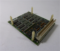
The IC697MEM717C expands the user memory capacity of GE Fanuc 90-70 series PLCs by adding 512 KB of high-speed CMOS RAM. It allows engineers to store larger logic programs, extensive data tables, and complex motion profiles that exceed the base CPU memory limits.Unlike EEPROM cartridges, this module uses volatile memory backed by a battery, offering faster read/write speeds during execution. Field logs show it handles frequent data logging tasks without slowing down the CPU scan time, provided the battery is maintained.
Installation & Configuration Guide
Preparation (10 min)
- Power down the PLC rack. Wait 30 seconds for capacitors to discharge.
- Ground yourself with an ESD wrist strap. Memory chips are highly sensitive to static discharge.
- Identify an empty slot in the universal backplane. Any slot works, but keep it near the CPU for easier cable management if using external battery backups.
Removal (5–10 min)
- If a memory cartridge cover is present, remove it.
- Unscrew the two mounting screws securing the module to the chassis frame.
- Gently pull the module straight out. Do not twist; the 96-pin backplane connector is fragile.
- Critical: If replacing a live module, ensure you have a backup of the program on a PC or floppy/flash card before removal. Data will be lost if the battery is dead.
Installation (10 min)
- Align the IC697MEM717C guide rails with the chosen slot.
- Push firmly until the connector seats fully. Ensure no gap exists between the module and the backplane.
- Secure the two mounting screws. Torque to 0.5 Nm (4.4 lb-in).
- Install a fresh battery if the existing one is older than 3 years or if the “BAT” LED was active on the CPU.
Power-On & Test (10 min)
- Restore power to the rack.
- Check the CPU “OK” and “BAT” LEDs. A solid green “OK” indicates successful recognition.
- Connect Proficy Machine Edition (or Logicmaster 90-70).
- Perform a “Verify” operation. The software should report the total available memory as Base + 512 KB.
- Run a test write to a register in the new memory space to confirm read/write integrity.
Troubleshooting Quick Reference
| Symptom | Probability | Action |
|---|---|---|
| CPU BAT LED On | High | Replace the module’s internal battery immediately. Program is at risk if power cycles. |
| Memory Fault Error | Medium | Reseat the module. Clean backplane pins with compressed air. Check for bent pins. |
| Program Lost After Power Cycle | Critical | Battery failed or was removed while powered off. Restore from backup. Replace battery. |
| CPU Won’t Go to RUN Mode | Low | Memory configuration mismatch. Verify hardware config in software matches physical installation. |
| Intermittent Comm Errors | Low | Loose mounting screws causing vibration-induced disconnects. Re-torque screws. |
Dimensions, Mounting & Wiring Notes
- Dimensions: 14.5 cm (H) × 10.2 cm (W) × 16.8 cm (D) – Standard 90-70 single-slot width.
- Mounting: Slides into any universal backplane slot. Secured via two front-face screws.
- Terminal Notes: No external wiring terminals. Connects solely via the 96-pin backplane connector.
- Battery Access: Battery compartment is typically accessible from the front faceplate without removing the module (check specific revision). Use CR2032 or equivalent specified by OEM.
IC697MEM717C GE
FAQ
Q: Can I hot-swap the IC697MEM717C while the PLC is running?
A: No. This is volatile memory. Removing it while powered will cause an immediate CPU fault and likely crash the process. Always power down before installation or removal.Q: How do I know if my battery is getting weak?
A: The CPU module will illuminate a “BAT” or “Low Battery” LED. Some systems also trigger a specific fault bit in the status table. Check this LED during every maintenance round.Q: Does the “C” revision hold more data than the original MEM717?
A: No. The capacity remains 512 KB across all revisions (A, B, C). The “C” suffix indicates updated internal components for better reliability or manufacturing efficiency. Functionally, they are identical.Q: What happens if I lose power and the battery is dead?
A: You will lose the entire user program and all data stored in RAM. The CPU will revert to a factory-empty state. This is why maintaining a current backup on a PC is non-negotiable.Q: Can I use this memory module with a 90-30 series PLC?
A: No. The 90-70 and 90-30 series use different form factors and backplane connectors. This module only fits 90-70 universal backplanes.Q: Is a battery included with refurbished units?
A: We install a new battery during our refurbishment process and test retention. However, batteries degrade over time on the shelf. We recommend replacing the battery upon final installation in the field to ensure maximum life.
Quality Transparency Strategy (SOP)
1. Incoming Inspection
- Origin Verification: Validate serial number format against GE Fanuc production records.
- Anti-Counterfeit Check: Inspect PCB labeling, font quality, and component soldering integrity.
- Physical Inspection: Check for corrosion on the 96-pin connector and cracks in the plastic housing.
- Accessories Verification: Ensure battery compartment is intact and screw holes are not stripped.
2. Live Functional Testing
- Dedicated Test Rack: Installed in a GE 90-70 backplane with a compatible CPU (e.g., CPU780).
- Power-On Self-Test: Verify CPU recognizes the additional 512 KB immediately upon boot.
- Read/Write Simulation: Write a known data pattern to the entire 512 KB range, then read it back. Verify 100% match.
- Retention Test: Power down the rack for 1 hour. Power up and verify data persistence.
- Test Report Generated: Document memory size recognized, read/write success rate, and retention test result.
3. Electrical Testing
- Backplane Continuity: Verify continuity on all 96 pins to ensure no broken traces.
- Voltage Drop: Measure 5V DC at the module connector under load. Must be >4.75V.
- Insulation: Check isolation between connector pins and chassis ground (>10 MΩ).
4. Firmware/Revision Verification
- Record Revision: Photograph and log the “Rev C” label.
- Battery Voltage Check: Measure battery voltage before sealing. Must be >3.0V DC.
- Visual Record: Photo of the connector pins and battery compartment.
5. Final QC & Packaging
- QC Signature: Technician signs off on memory verification and retention test.
- Anti-static Sealed: Unit placed in ESD shielding bag with desiccant.
- Bubble Wrap + Carton: Double-boxed to protect connector pins from impact.
- QC Passed Label: Affixed with date, technician ID, and battery installation date.
- Statement: Function verified under test conditions. Battery life depends on field storage temperature and power-off frequency.
Technical Pitfall Guide
- Battery Neglect:
- Scenario: A plant shuts down for a weekend maintenance. The battery in the MEM717C was 4 years old.
- Result: Monday morning, the PLC starts with a blank program. Production is down for 6 hours while IT restores from a backup (which turned out to be 3 months old).
- Fix: Implement a strict battery replacement schedule every 3 years, regardless of LED status. Keep a local backup updated weekly.
- Static Discharge Damage:
- Detail: A technician installs the module without an ESD strap on a dry winter day.
- Risk: Latent damage to the CMOS chips. The module works for weeks, then starts throwing random memory errors.
- Prevention: Always use grounded wrist straps. Touch the chassis before handling the module.
- Incomplete Seating:
- Scenario: The module feels “close” but the screws are forced to align.
- Result: Intermittent communication faults. The CPU sometimes sees the memory, sometimes doesn’t.
- Fix: If screws don’t align easily, pull the module out and re-seat. Never force screws to pull the module into place; this bends pins.
- Confusing Volatile vs. Non-Volatile:
- Misconception: Assuming this module acts like a flash card (EEPROM).
- Reality: It is RAM. It needs power (or battery) to hold data.
- Rule: Never rely on this module for long-term archival storage without a battery and a separate backup copy.
- Slot Compatibility Confusion:
- Scenario: Trying to force this into a 90-30 rack.
- Result: Physical damage to the backplane connector.
- Check: Verify the rack series. 90-70 modules are wider and have a different pin layout than 90-30.