 Tel:
Tel:  Email:
  WhatsApp:
 Description
Key Technical Specifications
| Parameter | Specification |
|---|---|
| Processor Type | 32-Bit Intel i960 (or equivalent architecture) |
| Clock Speed | 80 MHz |
| User Memory | 128 KB (RAM) |
| Program Storage | Flash EPROM (Non-volatile) |
| Execution Speed | 0.4 ms/k Boolean instructions (Typical) |
| Serial Ports | 2 x RS-232/485 (Configurable) |
| Ethernet Port | 1 x 10Base-T (RJ45) – SRTP/Modbus TCP |
| Global Data | Supported (up to 128 words) |
| Fault Tolerance | Watchdog timer, Battery backup |
| Battery Life | 3–5 Years (CR2032 type) |
| Operating Temp | 0°C to 60°C (32°F to 140°F) |
| Power Consumption | 3.0 W (Typical @ 5V DC) |
| Mounting | Series 90-70 Single Slot |
| Certifications | UL, cUL, CE |
Product Introduction
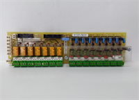
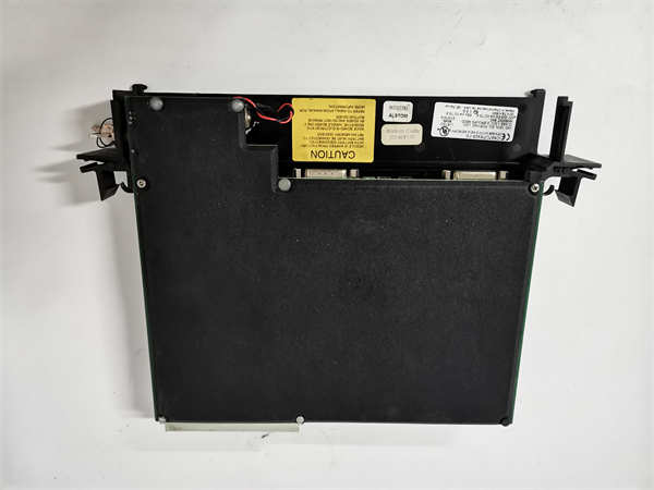
The GE IC697CPX928-FE serves as the high-performance controller for the Series 90-70 PLC platform, designed for applications requiring rapid scan times and substantial data capacity. It integrates dual serial ports and a native Ethernet interface, eliminating the need for separate communication coprocessors in many configurations.This “FE” revision offers optimized instruction execution compared to earlier 928 versions, achieving scan rates under 0.5ms for standard boolean logic blocks. Field installations in packaging lines demonstrate stable throughput even with heavy HMI polling on the Ethernet port. (Note: Ethernet speed is limited to 10Mbps). The unit requires a valid battery to retain user programs during power loss; always check the battery date code upon receipt.
Installation & Configuration Guide
Preparation (10 min)
Lock out and tag out the main rack power. Verify the slot assignment in your hardware configuration matches the physical layout. Inspect the new CPU for bent backplane pins. Have a fresh CR2032 battery ready if the existing one is older than 3 years. Ensure you have the correct serial cable (DB9 to DB9 or DB9 to USB adapter) for programming.Removal (5–10 min)
Disconnect all communication cables from the front ports. Remove the mounting screws securing the CPU to the chassis rail. Gently pull the module straight out. If resistance occurs, check for adjacent module interference. Immediately cover the exposed backplane slot with a blank filler if the rack will remain powered.Installation (10 min)
Align the IC697CPX928-FE guide rails with the chassis slot. Push firmly until the backplane connector seats fully. Secure the module with the two mounting screws; torque to 0.6 Nm to prevent vibration loosening. Reconnect communication cables, ensuring the Ethernet clip clicks into place. Verify the DIP switches (if present on this revision) match the required boot mode (usually “Run”).Power-On & Test (10 min)
Restore 5V DC power to the rack. Observe the LED sequence: PWR (Green), OK (Green flash), RUN (Green). The “FAULT” LED should remain off. If the “BATT” LED is red, replace the battery immediately. Connect via Proficy Machine Edition or Logicmaster 90-70. Perform a “Verify” operation to ensure the program in the CPU matches your source file. Check the Ethernet status lights for link activity.
Troubleshooting Quick Reference
| Symptom | Probability | Action |
|---|---|---|
| FAULT LED Red (Steady) | High | Corrupt user program or hardware failure. Clear memory and reload program. |
| OK LED Flashing Green | Medium | Boot loop or battery failure. Replace battery; check DIP switch settings. |
| No Ethernet Link | High | Cable fault or IP mismatch. Ping the CPU IP from a laptop; replace Cat5 cable. |
| Random Resets | Medium | 5V Backplane voltage dip. Measure voltage at the CPU terminals under load. |
| Serial Comm Errors | Low | Baud rate mismatch or wiring error. Verify pinout (2/3/5) and parity settings. |
Dimensions, Mounting & Wiring Notes
- Dimensions: Single-slot width (approx. 30mm W x 160mm H x 180mm D).
- Mounting: Secured via two front-face screws to the Series 90-70 chassis rail.
- Terminal Notes: Ethernet uses standard RJ45. Serial ports use DB9 connectors. Shielded cables are recommended for serial lines longer than 5 meters to prevent noise-induced data corruption. Do not daisy-chain power to the CPU; it draws directly from the backplane.

IC697CPX928-FE GE
FAQ
Q: Will the IC697CPX928-FE work in an older Series 90-60 chassis?
A: No. This CPU is designed exclusively for the Series 90-70 backplane architecture. The pinout and communication protocols are incompatible with the 90-60 series.Q: How do I know if my program is lost when power goes off?
A: If the “BATT” LED is green, the battery is holding the RAM. If it is red or off, the program is at risk. We recommend storing a copy in the Flash EPROM or on a PC as a backup.Q: Can I use a standard USB-to-Serial adapter for programming?
A: Yes, but ensure you install the correct drivers. Some cheap adapters struggle with the specific handshaking signals of the 90-70 series. Industrial-grade adapters are preferred.Q: What does the “-FE” suffix mean?
A: It denotes a specific hardware revision with updated components, often including enhanced Ethernet firmware capabilities. It is a direct drop-in replacement for non-FE 928 models, but always backup your program before swapping.Q: I see a faint burning smell near the CPU. Is this normal?
A: No. A faint dust smell might occur if the unit was stored in a dirty environment and heats up, but a sharp electrical smell indicates a component failure. Power down immediately and inspect for scorch marks.
Quality Transparency Strategy (SOP)
1. Incoming Inspection
We validate the serial number and “-FE” revision against OEM discontinuation records. Anti-counterfeit checks include examining the PCB silk screen quality, font consistency on chips, and the texture of the faceplate plastic. Physical inspection focuses on the condition of the DB9 and RJ45 ports (broken pins are common). We verify the battery holder is intact and not corroded.2. Live Functional Testing
Each IC697CPX928-FE is installed in a dedicated Series 90-70 test rack. We perform a full power-on self-test (POST). A communication handshake is established via both Serial and Ethernet ports simultaneously. We simulate a full I/O rack toggle to stress the processor scan cycle. A 24-hour continuous load test runs a complex math and comparison script to detect thermal instability. A test report is generated for each unit.3. Electrical Testing
Insulation resistance is measured (>10 MΩ @ 500V) between the logic ground and the metal faceplate. Ground continuity is verified from the mounting holes to the internal ground plane. We monitor the 5V current draw to ensure it remains within the 3.0W ±10% specification during peak scanning.4. Firmware Verification
We read the existing firmware version and compare it to the last known stable release from GE archives. If the unit contains a corrupted or beta version, we re-flash it using official tools. Photos are taken of any internal jumpers or DIP switches before resetting them to factory defaults.5. Final QC & Packaging
A senior technician signs the final QC checklist. The module is sealed in an anti-static bag with a new battery included (if the old one was marginal). We use double-wall cartons with custom foam inserts to protect the protruding connectors. A “QC Passed” label with the test date and load profile is applied.
Function verified under test conditions.
Technical Pitfall Guide
Firmware/Revision Mismatch
While the 928-FE is backward compatible, mixing it with very old I/O modules (pre-1995) can sometimes cause timing issues in global data tables. Scenario: A plant replaced a failed 928 with a 928-FE and experienced intermittent I/O drops. The issue was resolved by updating the GDT configuration in the software. Always review the GDT map after a CPU swap.Battery Failure Oversight
Technicians often ignore the “BATT” LED during installation. If the battery is dead, the first power cycle after installation will wipe the user program. Warning: Replace the battery before powering up if the LED indicates low voltage, or immediately upon receipt if the unit has been in storage.Ethernet Cable Quality
The 10Base-T port is sensitive to cable quality. Using modern high-speed cables is fine, but damaged shielding or incorrect crimping causes packet loss. Tip: Use a cable tester to verify all 4 pairs are continuous before blaming the CPU port.Backplane Voltage Drop
Adding a high-speed CPU to a rack with aging power supplies can cause the 5V rail to dip below 4.75V during peak scans. This triggers random resets. Action: Measure the 5V voltage at the CPU slot while forcing a maximum logic scan. If <4.8V, upgrade the rack power supply.ESD Damage to Ports
The DB9 and RJ45 connectors are vulnerable to electrostatic discharge. Plugging in cables without grounding can damage the transceiver chips. Observation: A common failure mode is having the CPU run fine but failing to establish a comms link. Always touch the chassis ground before connecting cables.