 Tel:
Tel:  Email:
  WhatsApp:
 Description
Key Technical Specifications
| Parameter | Specification |
|---|---|
| Slot Count | 10 Universal Slots |
| Compatible Series | GE Fanuc 90-70 Series |
| Backplane Bus | 90-70 Series Parallel Bus |
| Max Power Supply | Supports up to 35A (IC697PWR710 series) |
| Mounting Orientation | Horizontal or Vertical (with kit) |
| Material | Steel chassis with aluminum backplane |
| Connector Type | 96-pin DIN 41612 per slot |
| Operating Temp | 0°C to 60°C (32°F to 140°F) |
| Humidity Range | 5% to 95% non-condensing |
| Dimensions (Approx) | 48.3 cm (W) × 19.5 cm (H) × 15.0 cm (D) |
| Weight | Approx. 4.5 kg (9.9 lbs) empty |
| Certification | UL, CE, C-Tick |
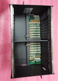
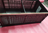
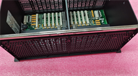
Product Introduction
The IC697CHS770 is a 10-slot universal rack designed to house the complete complement of GE Fanuc 90-70 series PLC components. It provides the structural mounting and electrical backplane connections required for system operation.This chassis features a robust steel frame and a gold-plated aluminum backplane that ensures reliable signal integrity across all ten slots. Field installations confirm its ability to support high-density I/O configurations without signal degradation over long distances. (Note: The “universal” designation means any slot can accept any module type, offering maximum flexibility.)
Installation & Configuration Guide
Preparation (10 min)
Select a mounting location with adequate ventilation. Ensure the panel cutout matches the rack dimensions (check the template in the manual). Gather mounting hardware (M4 or M5 bolts depending on panel thickness). Verify you have the correct power supply and CPU for the 10-slot configuration. Don’t forget the grounding strap.
Removal (5–10 min)
If replacing an existing rack, power down the entire system. Label every cable and module position. Remove modules one by one, placing them in anti-static bags. Unscrew the rack from the panel. Lift carefully; even empty, it has sharp edges. Inspect the old backplane for burnt pins before discarding.
Installation (10 min)
Insert the IC697CHS770 into the panel cutout. Secure it with four mounting bolts at the corners. Torque to 2.5 Nm. Install the power supply in the leftmost slot (Slot 1). Insert the CPU in Slot 2 (or Slot 1 if using a combined PSU/CPU slot arrangement, though typically PSU is separate). Slide in I/O modules firmly until they lock.
Power-On & Test (10 min)
Connect the main ground wire first. Then connect AC input to the power supply. Energize the system. Check the power supply LED. If green, proceed to check CPU status. Use a multimeter to measure 5V DC at various slot test points to ensure backplane continuity. Voltage drop should be less than 0.1V from Slot 1 to Slot 10.
Troubleshooting Quick Reference
| Symptom | Probability | Action |
|---|---|---|
| No Power to Any Slot | High | Check main AC input and power supply unit. Verify rack ground connection. |
| Intermittent I/O Faults | Medium | Inspect backplane pins for corrosion or bending. Reseat modules. |
| Voltage Drop at Far Slots | Medium | Calculate total current draw. High load on 10-slot racks can cause drop at Slot 10. |
| Module Not Recognized | Low | Check for bent pins in the specific slot. Try moving the module to Slot 3. |
| Physical Damage | Critical | Inspect for cracked solder joints on the backplane. Replace rack if found. |
Dimensions, Mounting & Wiring Notes
- Dimensions: 48.3 cm (W) × 19.5 cm (H) × 15.0 cm (D) approx.
- Mounting: Panel mount via four corner holes. Requires 19-inch rack mount kit for standard cabinets.
- Terminal Notes: No field wiring terminals on the rack itself. All wiring connects to individual modules.
- Clearance: Maintain 10 cm clearance on all sides for airflow. The metal chassis acts as a heat sink.
IC697CHS770 GE
FAQ
Can I mix 90-30 and 90-70 modules in this rack?
No. The backplane pinout and physical keying are different. 90-30 modules will not fit or function in the IC697CHS770. Attempting to force them will damage the connectors.I have a 10-slot rack but only need 4 slots. Can I leave the rest empty?
Yes. Empty slots do not consume power or affect operation. However, you must install filler panels (IC697ACC701) to maintain proper airflow and prevent dust accumulation. We’ve seen bugs crawl into open slots and cause shorts.How do I know if the backplane is damaged?
Visually inspect the gold pins inside each slot. Look for blackening, bending, or missing pins. Use a multimeter to check continuity between the power supply output and the farthest slot. High resistance indicates a bad backplane trace.Is this rack compatible with redundancy systems?
Yes, but redundancy requires specific CPU and synchronization modules. The rack itself is passive. Ensure your power supply has enough capacity for the redundant CPU pair.What is the maximum current this backplane can handle?
The backplane traces are rated for the maximum output of the largest supported power supply (35A). However, voltage drop becomes significant at high loads across 10 slots. Distribute high-current modules near the power supply.Can I mount this rack vertically?
Yes, but you need the specific vertical mounting kit. Ensure modules are secured tightly, as gravity can cause heavy modules to sag over time. We recommend horizontal mounting for vibration-heavy environments.Does it come with a ground bar?
No. The chassis has a ground screw, but you must provide the external ground bar and wiring. Proper grounding is critical for noise immunity. Don’t skip this step.
Quality Transparency Strategy (SOP)
1. Incoming Inspection
We verify the model number and serial number labels. Anti-counterfeit checks include examining the weld quality and paint finish. Physical inspection focuses on the backplane connector pins; we use a magnifying lens to check for bent or corroded pins. We verify the presence of mounting holes and threads.2. Live Functional Testing
Since the rack is passive, testing involves continuity and insulation checks. We mount a known-good power supply and a load module. We measure voltage at Slot 1 and Slot 10 under a 10A load. The difference must be within 0.2V. We simulate vibration by tapping the chassis while monitoring continuity. A test report documents voltage drop and physical condition.3. Electrical Testing
Insulation resistance is measured (>10 MΩ @ 500V between backplane traces and chassis). Ground continuity is checked from the ground screw to every mounting hole. Hi-pot testing is not typically performed on passive backplanes unless specified.4. Firmware Verification
Not applicable. We document the hardware revision if visible on the backplane label. Photos are taken of the internal backplane structure and pin conditions.5. Final QC & Packaging
A QC technician signs the continuity test report. The rack is wrapped in heavy-duty bubble wrap to protect the exposed backplane pins. Corner protectors are added. A “QC Passed” label with test data is attached. Function verified under test conditions; field performance depends on proper module installation.
Technical Pitfall Guide
Firmware Mismatch
Not applicable for racks, but module compatibility is key. Users sometimes try to install newer RX7i modules in this 90-70 rack. They physically fit but electrically fail. Always check the series designation on the module label.DIP/Jumper Misconfiguration
Racks have no jumpers, but power supply jumpers installed in the rack matter. Setting the wrong voltage on the PSU installed in this rack can destroy the backplane traces. Double-check PSU settings before inserting into the CHS770.Terminal Incompatibility
The issue here is connector incompatibility. Forcing a module with misaligned keys can bend the delicate backplane pins. Once bent, restoring contact is nearly impossible without specialized tools. Always align the guide rails perfectly before pushing.Power Supply Capacity Margin
A 10-slot rack encourages filling all slots. Users often exceed the 35A limit of the power supply. This causes voltage drop at the far end (Slot 10), leading to erratic behavior. Calculate the total load before filling all 10 slots. You might need a second rack.ESD Damage Risk
While the rack is metal, the backplane traces are sensitive to static discharge during module insertion. Always ground yourself before touching the exposed backplane. A static spark can carbonize a trace, causing an intermittent fault that takes days to diagnose. We found a charred trace once that looked like a manufacturing defect but was ESD damage.