 Tel:
Tel:  Email:
  WhatsApp:
 Description
Key Technical Specifications
| Parameter | Specification |
|---|---|
| Processor Speed | 1 GHz |
| User Memory | 10 MB (Application + Data) |
| Max I/O Capacity | 8,192 discrete points (local + remote) |
| Analog Channels | Up to 256 channels (dependent on modules) |
| Communication Ports | 2 x Ethernet (10/100 Mbps), 1 x Serial (RS-232/485) |
| USB Port | 1 x Type B (for programming) |
| Power Requirement | 5 V DC @ 1.2 A (typical backplane load) |
| Operating Temp | 0°C to 60°C (32°F to 140°F) |
| Protocol Support | Modbus TCP/IP, SRTP, EGD, OPC, Genius Bus (via adapter) |
| Redundancy | Not supported on CRU320 (Single CPU only) |
| Mounting | RX3i Universal Backplane (Slots 1-8) |
| Certifications | UL, cUL, CE, C-Tick (Verify “EL” specific marks) |
Product Introduction
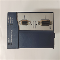
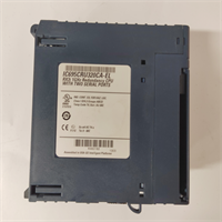
The IC695CRU320CA-EL is a robust controller within the PACSystems RX3i family, designed to bridge the gap between simple PLCs and high-end PCs. It features a 1 GHz processor capable of executing complex logic and motion control tasks with scan times typically under 1 ms for moderate programs.With 10 MB of user memory, it accommodates large-scale applications that require extensive data logging or complex mathematical functions. The integrated dual-port Ethernet switch simplifies network topology, allowing daisy-chaining of devices without an external switch. The “CA-EL” designation suggests a unit configured for specific international markets or distributor requirements, but it retains the full functional capability of the standard CRU320 architecture.
Installation & Configuration Guide
Preparation (10 min)
- Power down the RX3i rack. Verify 0 V DC at the power supply terminals.
- Ground yourself using an ESD wrist strap. The CPU contains sensitive CMOS components.
- Confirm the backplane slot is free (Slot 1 is recommended for single CPU systems, though RX3i allows flexible slotting).
Removal (5–10 min)
- Disconnect Ethernet and serial cables. Label them clearly (Port 1 vs. Port 2).
- Press the ejector latches on the top and bottom of the module.
- Slide the module out smoothly. Avoid wiggling to prevent bending backplane pins.
Installation (10 min)
- Align the IC695CRU320CA-EL guide rails with the chassis slots.
- Push firmly until the module seats completely against the backplane. Feel for the solid stop.
- Engage the locking levers. They must click into place. If they resist, re-seat the module.
Power-On & Test (10 min)
- Restore power to the rack. Watch the CPU LEDs immediately.
- The OK LED should turn solid green within 15 seconds. Flashing red indicates a firmware mismatch or battery issue.
- Connect a laptop via USB or Ethernet. Launch Proficy Machine Edition.
- Perform a “Verify” operation to check hardware configuration against the loaded project.
Troubleshooting Quick Reference
| Symptom | Probability | Action |
|---|---|---|
| OK LED Flashing Red | High | Check battery voltage (replace if < 3.0V). Verify firmware version matches project requirements. |
| No Comm via Ethernet | Medium | Inspect link lights. Ensure IP address is unique and subnet mask is correct. |
| CPU Won’t Seat | Low | Inspect backplane pins for debris. Clean with compressed air only. |
| Random Faults | Medium | Measure backplane 5V supply under load. Voltage drop below 4.75V causes instability. |
| Battery Alarm | High | Replace CR2032 battery immediately while powered up to retain RAM content. |
Dimensions, Mounting & Wiring Notes
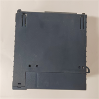
- Dimensions: 14.5 cm (H) × 10.2 cm (W) × 16.8 cm (D) – includes handle and connectors.
- Mounting: Slides into RX3i universal backplane slots. Uses integrated locking levers; no screws required.
- Terminal Notes: Ethernet ports use standard RJ45 connectors. Serial port is D-Sub 9-pin male.
- Warning: Do not hot-swap this CPU unless specifically configured and supported by the system architecture (generally not recommended for non-redundant CRU320 setups).
IC695CRU320CA-EL GE
FAQ
Q: What does the “CA-EL” suffix mean?
A: Suffixes like “CA” and “EL” often denote specific distributor configurations, regional certifications (e.g., specific CE variants), or factory-loaded firmware bundles. Functionally, it operates as a standard IC695CRU320. Always verify the specific firmware version on the label before integrating into an existing project.Q: Can I use this to replace an older IC693CPU model from the 90-30 series?
A: No. The physical form factor and backplane pinout differ between the 90-30 series and PACSystems RX3i. You would need to migrate the entire rack and I/O modules.Q: How much memory does this have?
A: The IC695CRU320 series comes with 10 MB of user memory, which is shared between the application logic and data tables.Q: Is this unit new or refurbished?
A: Availability varies. We stock both new surplus and refurbished units. Refurbished items undergo a 24-hour load test and include a 1-year warranty. Check the specific listing status.Q: Does this support redundancy?
A: No, the CRU320 is a single-CPU controller. For redundancy, you would need to look at the RX7i series (e.g., IC698CRE040) or specific high-availability RX3i configurations (if available with other CPU models).Q: What software do I need to program this?
A: You need GE Fanuc Proficy Machine Edition (PME). Ensure your version of PME supports the specific firmware revision loaded on the “CA-EL” unit.
Quality Transparency Strategy (SOP)
1. Incoming Inspection
- Origin Verification: Cross-check serial number format against known Emerson/GE production batches.
- Anti-Counterfeit Check: Inspect holographic labels, font consistency on casing, and PCB build quality.
- Physical Inspection: Look for burnt components, swollen capacitors, or bent backplane pins.
- Suffix Verification: Specifically photograph and log the “CA-EL” suffix to ensure it matches the order and to track regional variants.
2. Live Functional Testing
- Dedicated Test Rack: Loaded into a verified RX3i universal backplane with dummy load modules.
- Power-On Self-Test: Apply 5V DC. Verify “OK” and “RUN” LED sequences.
- Memory Test: Write/Read patterns to the full 10 MB memory space to check for bad sectors.
- Comm Test: Establish connection via both Ethernet ports and USB. Test Modbus TCP and SRTP protocols.
- 24h Load Test: Run a continuous logic scan loop for 24 hours to detect thermal instability.
- Test Report Generated: Document firmware version, MAC address, and test results.
3. Electrical Testing
- Backplane Continuity: Verify continuity on all backplane pins.
- Voltage Drop: Measure 5V DC at the module connector under load. Must be >4.75V.
- Ground Continuity: Verify <0.1 Ω resistance from ground terminal to chassis.
4. Firmware/Revision Verification
- Record Revision: Photograph and log the specific hardware revision and “CA-EL” marking.
- Firmware Version: Read and document the installed firmware version via software.
- Visual Record: Photo record of internal PCB condition (if opened for cleaning) and connector pins.
5. Final QC & Packaging
- QC Signature: Technician signs off on load test and memory verification.
- Anti-static Sealed: Unit placed in ESD shielding bag.
- Bubble Wrap + Carton: Double-boxed with 2-inch foam padding.
- QC Passed Label: Affixed with date, technician ID, and firmware version.
- Statement: Function verified under test conditions. Specific field compatibility depends on total system load and firmware matching.
Technical Pitfall Guide
- Firmware Mismatch:
- Scenario: An engineer tries to download a project created in PME v9.0 to a CPU running very old firmware (common in “CA-EL” legacy stock).
- Result: Download fails with “Hardware Mismatch” error.
- Fix: Always check the firmware version on the unit label or via online connection before purchasing. Update firmware if necessary (requires license and care).
- Battery Failure Leading to Data Loss:
- Detail: The CRU320 uses volatile RAM backed by a battery. If the battery dies and power is cut, the program is lost.
- Risk: Unexpected shutdowns after long periods of operation with an old battery.
- Prevention: Replace the CR2032 battery proactively every 3-5 years or immediately upon seeing the “BAT” LED.
- Ethernet IP Conflicts:
- Scenario: The CPU comes with a default IP or a previous user’s IP. Connecting it to a live network causes a conflict.
- Result: Network instability, loss of HMI connection.
- Fix: Always isolate the CPU on a bench network first to assign a unique IP address before connecting to the plant floor.
- Overloading the Backplane:
- Scenario: Adding too many high-current I/O modules to a rack powered by a marginal power supply, causing the CPU to reset due to voltage sag.
- Result: Intermittent faults, “Low Voltage” errors.
- Rule: Calculate total backplane current draw. Ensure the power supply has 20% headroom.
- Incorrect Slot Usage (Legacy Habits):
- Detail: While RX3i is flexible, some legacy configurations or specific network adapters expect the CPU in Slot 1.
- Risk: Confusion during troubleshooting or specific bootloader issues.
- Best Practice: Install the CPU in Slot 1 unless there is a compelling reason not to, to maintain consistency with standard documentation.