
 Tel:
Tel:  Email:
  WhatsApp:
 Description
Key Technical Specifications
| Parameter | Specification |
|---|---|
| Network Protocol | DeviceNet (ODVA Standard) |
| Role | Master / Scanner |
| Max Nodes | 64 (Address 0–63) |
| Baud Rates | 125 kbps, 250 kbps, 500 kbps (Auto-detect or Fixed) |
| I/O Capacity | Up to 2048 bytes Input / 2048 bytes Output (Total dependent on config) |
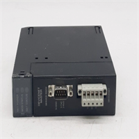
| Connection Type | 5-pin Phoenix Contact Terminal Block (Removable) |
| Power Supply | Powered from Backplane (5V DC); Network Power separate (24V DC) |
| MAC ID Setting | Rotary Switches (0–63) on front panel |
| Status LEDs | MOD (Module), NET (Network), NS (Network Status), MS (Module Status) |
| Operating Temp | 0°C to 60°C (32°F to 140°F) |
| Power Consumption | 1.2 W (Typical @ 5V DC) |
| Isolation | 500V AC isolation between backplane and network |
| Certifications | UL, cUL, CE, ODVA Conformance Tested |
Product Introduction
The GE IC693DNM200-BD is the primary interface for connecting Series 90-30 PLCs to the DeviceNet industrial network. It allows the PLC to control and monitor a wide array of third-party DeviceNet devices such as variable frequency drives (VFDs), motor starters, and smart sensors without hardwiring every signal.The “-BD” revision features improved noise immunity and faster scan updates compared to early “AA” versions. It supports both polled and change-of-state (COS) data transfer methods. Field installations show stable communication at 500kbps over distances up to 100 meters when proper cabling is used. (Note: Network power (24V DC) must be supplied separately to the DeviceNet trunk line; this module does not power the network itself). Configuration is handled via PLC registers (%I, %Q, %AI, %AQ) mapped to specific device assemblies.
Installation & Configuration Guide
Preparation (10 min)
Power down the Series 90-30 rack. Verify the slot location (any slot except the power supply slot). Set the MAC ID rotary switches on the front panel to the desired node address (0–63) before powering up. Ensure you have the correct DeviceNet cable (thick or thin media) and terminators. Check that the 24V DC network power supply is ready.Removal (5–10 min)
Disconnect the DeviceNet cable from the terminal block. Unscrew the terminal block if necessary (some versions allow unplugging the block directly). Remove the mounting screws securing the module to the rail. Slide the module out gently. Inspect the backplane pins for damage.Installation (10 min)
Slide the IC693DNM200-BD into the chosen slot until it seats firmly against the backplane. Secure with mounting screws. Reattach the terminal block (if removed) and connect the DeviceNet wires: Shield to Ground, V+ (Red) to 24V+, V- (Black) to 24V-, Data+ (White), Data- (Blue). Ensure the shield is grounded at one end only to prevent ground loops. Verify the MAC ID switches match your configuration software.Power-On & Test (10 min)
Apply power to the PLC rack and the DeviceNet network. Observe LEDs: MS (Module Status) should be Green (steady). NS (Network Status) will flash green while initializing, then turn steady green when online with all configured nodes. If NS turns Red, check baud rate mismatch or missing terminators. Use Proficy Machine Edition or Logicmaster 90-30 to verify I/O mapping. Force a toggle on a connected output device to confirm control.
Troubleshooting Quick Reference
| Symptom | Probability | Action |
|---|---|---|
| MS LED Red | High | Module hardware fault or firmware corruption. Reseat module; cycle power. |
| NS LED Red (Flashing) | High | Connection timeout with one or more slaves. Check slave power and wiring. |
| NS LED Off | Medium | No network power or baud rate mismatch. Measure 24V on V+/V- terminals. |
| Intermittent Comm Loss | Medium | Missing terminator or loose shield. Install/verify 121Ω terminators at both ends. |
| Specific Node Failing | Low | Duplicate MAC ID or bad slave device. Check rotary switches on all nodes. |
Dimensions, Mounting & Wiring Notes
- Dimensions: Single-slot width (approx. 30mm W x 100mm H x 150mm D). Fits standard Series 90-30 racks.
- Mounting: Slides into backplane; secured by two front-face screws.
- Terminal Notes: Uses a 5-position removable terminal block. Wire size: 16–24 AWG stranded. Torque: 0.5–0.6 Nm. Critical: Do not connect 24V network power to the PLC backplane; keep networks isolated. Shield drain wire must be connected to the chassis ground lug.
IC693DNM200-BD GE
FAQ
Q: Can this module power my DeviceNet devices?
A: No. The IC693DNM200-BD only provides communication. You must provide a separate 24V DC power supply for the DeviceNet trunk line to power the slaves.Q: What happens if I change the MAC ID switch while powered?
A: The change will not take effect until the next power cycle. The module reads the switches only at boot. Always power down before changing addresses.Q: Is the “-BD” version different from “-AA”?
A: Yes, “-BD” is a later revision with updated components for better reliability. They are functionally interchangeable in most applications, but always verify firmware compatibility if mixing revisions in a large system.Q: How many devices can I connect?
A: Technically up to 64 nodes (addresses 0–63). However, practical limits depend on the total I/O data size and bandwidth usage. Keep total data under the module’s capacity (approx. 2KB I/O).Q: My NS LED is flashing green slowly. What does this mean?
A: This usually indicates the module is waiting for a connection to a specific slave that isn’t responding. Check the configuration table for “Expected” vs “Actual” connections.
Quality Transparency Strategy (SOP)
1. Incoming Inspection
We verify the serial number and “-BD” revision. Anti-counterfeit checks focus on the quality of the rotary switches, terminal block plastic, and label printing. Physical inspection includes checking for bent pins on the backplane connector and ensuring the terminal block screws are not stripped. We verify the presence of the status LEDs.2. Live Functional Testing
Each module is installed in a Series 90-30 test rack connected to a live DeviceNet simulator with multiple virtual nodes. We test communication at all three baud rates (125K, 250K, 500K). We simulate node failures to verify error handling and LED indicators. A 24-hour continuous data exchange test runs to ensure stability under load. A test report logs all successful connections and error recovery times.3. Electrical Testing
Insulation resistance is measured (>10 MΩ @ 500V) between the network terminals and the backplane ground. Ground continuity is verified. We monitor the 5V current draw to ensure it stays within the 1.2W spec. We also verify the isolation barrier integrity.4. Firmware Verification
We read the internal firmware version and compare it to known stable releases. If corrupted, we re-flash using official GE tools. Photos are taken of the rotary switch settings and internal jumpers (if any) before resetting.5. Final QC & Packaging
A senior technician signs the QC checklist. The module is sealed in an anti-static bag with the terminal block attached. We use double-wall cartons with foam inserts to protect the terminal block from impact. A “QC Passed” label with test summary is applied.
Function verified under test conditions.
Technical Pitfall Guide
Missing Terminators
DeviceNet requires 121Ω resistors at both physical ends of the trunk line. Scenario: A technician added a new drop line but forgot to reinstall the terminator at the far end, causing reflections and intermittent comm loss at 500kbps. Rule: Always verify terminators are present at the extreme ends of the network, not just near the master.Network Power vs. Logic Power
Confusing the 24V network power with the PLC’s 24V sensor power can lead to ground loops or insufficient current for devices. Warning: Use a dedicated 24V supply for the DeviceNet trunk if possible, or ensure the common supply has enough capacity and proper grounding.MAC ID Conflicts
Setting two devices to the same MAC ID causes bus arbitration failures, stopping all communication. Tip: Create a physical map of all MAC IDs before installation. Double-check rotary switches visually before powering up.Baud Rate Mismatch
All devices on the network must run at the same baud rate. The master does not auto-negotiate speed with slaves. Check: Verify the dip switches or software config on every slave matches the master’s setting.Shield Grounding Issues
Grounding the shield at both ends can create a ground loop, introducing noise that corrupts data. Best Practice: Ground the shield at one end only (usually the master end) unless high-frequency interference dictates otherwise per ODVA guidelines.


