
 Tel:
Tel:  Email:
  WhatsApp:
 Description
Key Technical Specifications
| Parameter | Specification |
|---|---|
| Network Protocol | GE Genius Bus (Proprietary) |
| Role | Bus Controller (Master) |
| Max Nodes | 31 Genius Blocks per GBC |
| Baud Rates | 19.2, 38.4, 76.8, 153.6 kbps (Configurable via switches/software) |
| I/O Capacity | Depends on connected blocks (Typically up to 256 bytes Input/Output per GBC) |
| Connection Type | 9-pin D-Sub (Female) Connector on front panel |
| Power Supply | Powered from Backplane (5V DC); Bus power separate (24V DC typically) |
| Address Setting | DIP Switches or Software Configuration (GBC Address 1–8 supported in multi-GBC systems) |
| Status LEDs | OK, RUN, FLT, COMM, BUS FAULT |
| Operating Temp | 0°C to 60°C (32°F to 140°F) |
| Power Consumption | 1.5 W (Typical @ 5V DC) |
| Isolation | 1500V AC isolation between backplane and Genius Bus |
| Certifications | UL, cUL, CE |
Product Introduction
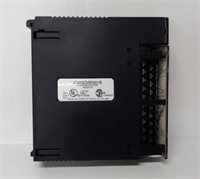
The GE IC693CMM301 is the critical link for Series 90-30 PLCs utilizing the Genius I/O system. It allows the central CPU to communicate with remote racks of I/O located hundreds of feet away, reducing wiring costs and complexity. The module manages data exchange, fault reporting, and configuration for all connected Genius blocks.This unit supports both global data exchange (automatic I/O mapping) and direct serial communication commands. Field data shows robust performance in noisy industrial environments due to the differential signaling of the Genius bus. The “-CMM301” model is the most common revision; later sub-revisions offer minor internal component updates but remain pin-compatible. (Note: The Genius bus requires termination resistors at the physical ends of the network, and proper shield grounding is critical for stability). Configuration is typically done via Proficy Machine Edition or the older Logicmaster 90-30 software.
Installation & Configuration Guide
Preparation (10 min)
Power down the Series 90-30 rack. Identify the slot for the GBC (any slot except power supply). If replacing an existing unit, note the DIP switch settings or software configuration for the GBC address and baud rate. Inspect the 9-pin connector for bent pins. Ensure you have the correct Genius bus cable (twisted pair with shield) and terminators (120Ω).Removal (5–10 min)
Disconnect the Genius bus cable from the 9-pin port. Remove the mounting screws securing the module to the rail. Slide the module out gently. Check the backplane pins for debris. If the system has multiple GBCs, label them to avoid address confusion.Installation (10 min)
Slide the IC693CMM301 into the designated slot until it seats firmly. Secure with mounting screws. Reconnect the Genius bus cable to the 9-pin port; ensure the locking screws are tightened to prevent vibration loosening. Connect the shield drain wire to the chassis ground lug. Verify that the baud rate DIP switches (if used) match the network settings. Ensure terminators are installed at the far ends of the bus trunk.Power-On & Test (10 min)
Apply power to the PLC rack and the Genius bus network. Observe LEDs: OK and RUN should be Green (steady). The COMM LED should flash during activity. If the BUS FAULT LED is red, check for open circuits, missing terminators, or address conflicts. Use Proficy Machine Edition to go online and verify that all configured Genius blocks are reporting “Good” status. Force a change on a remote output to confirm end-to-end control.
Troubleshooting Quick Reference
| Symptom | Probability | Action |
|---|---|---|
| BUS FAULT LED Red | High | Open circuit, missing terminator, or short on the bus. Check cable continuity and terminators. |
| COMM LED Off | Medium | No activity or baud rate mismatch. Verify baud rate settings on GBC and all blocks. |
| Specific Block Fault | High | Failed Genius block or power loss to that block. Check 24V power to the remote rack. |
| Intermittent Errors | Medium | Shield grounding issue or noise. Verify shield is grounded at one end only (or per spec). |
| GBC Not Recognized by CPU | Low | Slot configuration mismatch in software. Verify hardware config matches physical slot. |
Dimensions, Mounting & Wiring Notes
- Dimensions: Single-slot width (approx. 30mm W x 100mm H x 150mm D). Fits standard Series 90-30 racks.
- Mounting: Slides into backplane; secured by two front-face screws.
- Terminal Notes: Uses a 9-pin D-Sub connector. Pinout: Typically Pin 2 (Data+), Pin 3 (Data-), Pin 5 (Common/Shield). Critical: Do not apply 24V power to the data pins. Use shielded twisted pair cable (Belden 9841 or equivalent). Terminate the bus with 120Ω resistors at the two physical extremes of the network.
IC693CMM301 GE
FAQ
Q: How many Genius blocks can one IC693CMM301 handle?
A: Up to 31 blocks per GBC. If you need more, you can install up to 8 GBCs in a single PLC rack (depending on CPU capability and slot availability), supporting over 200 blocks total.Q: Can I mix different baud rates on the same bus?
A: No. All devices (GBC and all Genius blocks) on a single continuous bus segment must operate at the same baud rate.Q: What is the difference between IC693CMM301 and IC693CMM302?
A: The CMM302 is an enhanced version with slightly faster processing or updated firmware capabilities. They are generally interchangeable, but always verify the specific feature set required by your application (e.g., specific global data table sizes).Q: My BUS FAULT light is on, but all cables look fine. What now?
A: Check for a broken terminator resistor or a Genius block that has failed internally and is pulling the bus down. Disconnect blocks one by one to isolate the fault. Also, verify that no two devices have the same Genius address.Q: Does this module provide power to the Genius blocks?
A: No. The GBC only provides communication. Each Genius block requires its own 24V DC power supply (or a shared supply with adequate capacity and proper wiring).
Quality Transparency Strategy (SOP)
1. Incoming Inspection
We validate the serial number and revision level. Anti-counterfeit checks include examining the 9-pin connector quality (plating, pin alignment), label font, and PCB silk screen. Physical inspection verifies the integrity of the DIP switches and mounting ears. We check for any signs of burn marks or capacitor leakage.2. Live Functional Testing
Each IC693CMM301 is installed in a Series 90-30 test rack connected to a simulated Genius bus with multiple virtual and physical Genius blocks. We test communication at all supported baud rates. We simulate bus faults (open, short, missing terminator) to verify error detection and LED indicators. A 24-hour continuous data exchange test runs to ensure stability. A detailed test report logs connection success rates and error recovery.3. Electrical Testing
Insulation resistance is measured (>10 MΩ @ 500V) between the bus connector pins and the backplane ground. Ground continuity is verified. We monitor the 5V current draw to ensure it stays within the 1.5W spec. Isolation barrier integrity is tested.4. Firmware Verification
We read the internal firmware version and compare it to known stable releases. If corrupted or obsolete, we update it using official GE tools. Photos are taken of the DIP switch settings and internal components before resetting.5. Final QC & Packaging
A senior technician signs the final QC checklist. The module is sealed in an anti-static bag. We use double-wall cartons with custom foam inserts to protect the 9-pin connector from bending. A “QC Passed” label with test summary is applied.
Function verified under test conditions.
Technical Pitfall Guide
Missing or Incorrect Terminators
The Genius bus is sensitive to reflections. Missing 120Ω terminators at the physical ends of the bus causes data corruption, especially at higher baud rates. Scenario: A plant extended the bus but forgot to move the terminator to the new end, resulting in intermittent faults. Rule: Always verify terminators are present ONLY at the two extreme physical ends of the trunk.Ground Loops via Shielding
Grounding the cable shield at both ends can create a ground loop, introducing noise that disrupts communication. Best Practice: Ground the shield at the GBC end (or per the specific site grounding plan), ensuring the remote end is isolated unless high-frequency noise dictates otherwise.Address Conflicts
Assigning the same Genius address to two different blocks causes bus arbitration failures. Tip: Maintain a strict address log. Double-check the rotary switches or dip switches on every remote block before energizing the bus.Baud Rate Mismatch
If the GBC is set to 153.6kbps but a remote block is hard-set to 38.4kbps, communication will fail completely. Check: Verify the configuration software settings match the physical switch settings on all devices.Power Sequencing Issues
Sometimes, powering up the remote Genius blocks before the PLC/GBC can cause timeout errors during the initial handshake. Observation: While usually resilient, some older systems prefer the GBC to be powered and running before the remote blocks initialize. If persistent faults occur on startup, try sequencing the power supplies.


