
 Tel:
Tel:  Email:
  WhatsApp:
 Description
Key Technical Specifications
| Parameter | Specification |
|---|---|
| Function | Signal Fanout for Redundant CPU Pairs |
| Ports/Channels | 8 (Indicated by “008” suffix – verify specific pinout) |
| CPU Support | Connects 2 CPUs (Primary & Secondary) to shared I/O |
| Transfer Time | Supports < 10ms bumpless transfer (system dependent) |
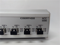
| Indicator LEDs | Status LEDs for Primary Link, Secondary Link, Fault, Active |
| Power Requirement | Typically powered via backplane or external 24V DC (Check label) |
| Operating Temp | 0°C to 60°C (32°F to 140°F) |
| Mounting | DIN Rail or Panel Mount (Often standalone or in specific chassis) |
| Cable Type | Shielded twisted pair for high-noise immunity |
| Protocol | Proprietary GE Redundancy Protocol / Genius Bus (if applicable) |
| Certifications | UL, cUL, CE (as part of the redundant system) |
Product Introduction
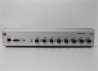
The IC690RFH008 is a vital component for implementing Hot Standby Redundancy in GE Fanuc 90-30 PLC systems. In critical industrial applications, a single CPU failure can result in costly downtime or safety hazards. This module acts as the intelligent switchgear that allows two identical CPUs to monitor the same process inputs and compete for control outputs.By utilizing the RFH008, the system ensures that if the Primary CPU detects an internal fault or loses communication, the Secondary CPU instantly assumes control without disrupting the connected I/O modules. The “008” designation suggests it supports up to 8 distinct I/O drops or communication links, making it suitable for medium-to-large distributed control systems requiring high availability.
Installation & Configuration Guide
Preparation (15 min)
- System Design: Verify that both CPUs are identical models (e.g., two IC693CPU372s) with matching firmware versions.
- Power Down: Ensure the entire redundancy rack and I/O drops are powered down.
- Cabling: Prepare shielded cables for connecting the CPUs to the RFH008 and the RFH008 to the I/O drops.
- Mounting: Secure the IC690RFH008 module on a DIN rail or panel near the CPU racks. Ensure adequate ventilation.
Wiring (20 min)
- CPU Connections: Connect the “Primary CPU” port on the RFH008 to the communications port of CPU #1. Connect the “Secondary CPU” port to CPU #2. Use the specified GE redundancy cables.
- I/O Drop Connections: Connect the 8 output ports of the RFH008 to the respective I/O scanner modules or remote drops.
- Grounding: Ensure the shield of all cables is grounded at one end (usually the RFH008 side) to prevent ground loops.
- Power: If the module requires external power, connect 24V DC to the designated terminals.
Configuration (20 min)
- Hardware Config: In Proficy Machine Edition (or Logicmaster 90-30), configure the hardware table to include the Redundancy option.
- Assign Roles: Define which CPU is Primary and which is Secondary in the software configuration.
- RFH Settings: Configure the RFH008 parameters (if dip switches or software config are available) to match the number of connected drops.
- Download: Download the redundancy configuration to both CPUs.
Power-On & Test (15 min)
- Power up the Primary CPU first, then the Secondary.
- Observe LEDs on the RFH008:
- Primary Link: Should be solid green.
- Secondary Link: Should be solid green (indicating sync).
- Active: Indicates which CPU is currently controlling the I/O.
- Failover Test: While the system is running, simulate a fault on the Primary CPU (e.g., remove its power or trigger a software fault).
- Verification: Confirm the Secondary CPU takes over immediately (bumpless transfer) and the “Active” LED switches. Check that outputs do not glitch.
Troubleshooting Quick Reference
| Symptom | Probability | Action |
|---|---|---|
| Secondary Link LED Off | High | Check cable between Secondary CPU and RFH. Verify Secondary CPU is powered and booted. |
| Fault LED Flashing | High | Mismatched CPU firmware versions or configuration error. Re-download config to both CPUs. |
| Outputs Glitch on Switchover | Medium | Transfer time too slow or I/O module not redundancy-capable. Verify I/O compatibility. |
| No Communication to Drops | Medium | Check wiring from RFH008 to I/O drops. Verify termination resistors are installed. |
| Primary Won’t Go Active | Low | Primary CPU has internal fault. Check CPU diagnostic bits. Force switchover via software if safe. |
| Intermittent Comm Errors | Low | Noise interference. Check cable shielding and grounding. Move away from VFDs. |
Dimensions, Mounting & Wiring Notes
- Dimensions: Approx. 10.0 cm (H) × 15.0 cm (W) × 8.0 cm (D) – Typical for standalone hubs.
- Mounting: Standard 35mm DIN Rail mount.
- Terminal Notes: Uses screw terminals or proprietary connectors for CPU and I/O links. Tighten screws to 0.5 Nm.
- Cable Length: Maximum cable length between CPU and RFH, and RFH and I/O, is typically 100m (verify specific protocol limits).
- Warning: Do not hot-swap the RFH008 module itself while the system is running. CPU hot-swapping is supported in redundancy mode, but the hub must be stable.
IC690RFH008 GE
FAQ
Q: Can I use the IC690RFH008 with non-redundant CPUs?
A: No. This module is specifically designed for pairs of CPUs configured in Hot Standby mode. Using it with a single CPU will result in errors or non-functional I/O.Q: What happens if the RFH008 module fails?
A: If the hub itself fails, both CPUs will lose communication with the I/O drops, causing a system stop. For ultimate reliability, some critical systems employ dual hubs, but typically the hub is considered a single point of failure unless mirrored.Q: Does this support “Bumpless” transfer?
A: Yes, when configured correctly with compatible I/O modules, the system maintains output states during the switchover, ensuring no physical disruption to the process (e.g., valves stay in position).Q: How many I/O drops can I connect?
A: The “008” suggests support for up to 8 drops or channels. Exceeding this limit may require additional hubs or a different model.Q: Is special software needed?
A: Yes, you need Proficy Machine Edition with the Redundancy option enabled/license. Standard logic configuration is insufficient; specific redundancy tables must be defined.Q: Can I mix CPU models in a redundant pair?
A: No. Both CPUs must be the exact same model number (e.g., two CPU372s) and preferably the same hardware revision and firmware version to ensure seamless synchronization.
Quality Transparency Strategy (SOP)
1. Incoming Inspection
- Visual Check: Inspect connector pins for bending or corrosion. Check housing for cracks.
- Label Verification: Confirm model number “IC690RFH008” and serial number legibility.
- Component Check: Look for signs of overheating, capacitor leakage, or burnt components on the PCB.
2. Live Functional Testing
- Redundancy Test Rig: Setup requires two compatible 90-30 CPUs, a power supply, and simulated I/O drops.
- Link Verification: Power up both CPUs. Verify RFH008 establishes links with both (Green LEDs).
- Sync Test: Monitor synchronization status via software. Ensure no sync errors.
- Failover Simulation: Physically disconnect the Primary CPU. Measure the time taken for the Secondary to become “Active”. Verify outputs remain stable.
- Restoration Test: Reconnect Primary CPU. Verify it syncs up and becomes “Standby” without disturbing the running Secondary.
- Load Test: Run the system under simulated load for 4 hours to check for thermal stability.
3. Electrical Testing
- Continuity: Test all input/output ports for continuity.
- Isolation: Verify electrical isolation between CPU ports and I/O ports.
- Power Draw: Measure current consumption to ensure it matches specifications.
4. Firmware/Config Verification
- Compatibility Check: Ensure the unit works with common firmware versions of 90-30 CPUs.
- Visual Record: Photograph the unit, labels, and test rig LED status during successful failover.
5. Final QC & Packaging
- QC Sign-off: Technician certifies successful failover test.
- ESD Protection: Pack in anti-static bag.
- Packaging: Double-box with foam to protect connectors.
- Documentation: Include a test report detailing the failover time and link stability.
Technical Pitfall Guide
- Single Point of Failure (The Hub):
- Risk: Relying on a single RFH008 for critical safety. If the hub dies, redundancy is lost.
- Mitigation: In ultra-critical apps, consider if a higher-level architecture (like RX3i redundancy) is more appropriate, or keep a spare RFH008 on hand for immediate replacement.
- Cable Shielding & Grounding:
- Detail: Redundancy comms are sensitive.
- Risk: Poor grounding causes intermittent sync loss, leading to unnecessary swapovers or system faults.
- Fix: Follow GE grounding specs strictly. Ground shields at the hub end only.
- Firmware Mismatch:
- Scenario: One CPU has older firmware than the other.
- Result: Sync fails. The system cannot enter redundancy mode.
- Prevention: Always flash both CPUs to the exact same firmware version before configuring redundancy.
- I/O Module Compatibility:
- Risk: Using standard I/O modules that do not support redundancy holding states.
- Consequence: Outputs may drop or flicker during switchover.
- Fix: Verify all I/O modules in the chain are rated for redundancy applications.
- Incorrect Dip Switch/Jumper Settings:
- Detail: Some hubs require manual configuration via dip switches for address or termination.
- Risk: Wrong settings prevent communication.
- Fix: Consult the specific hardware manual for the “008” variant switch settings before powering up.