 Tel:
Tel:  Email:
  WhatsApp:
 Description
Key Technical Specifications
| Parameter | Specification |
|---|---|
| Bus Type | GE Genius Global Data Bus (RS-485 based) |
| Max Blocks per Bus | 32 (including the GBC itself) |
| Supported Baud Rates | 93.75, 156.25, 187.5, 250, 500 Kbps (configurable) |
| Global Data Capacity | Up to 128 bytes Input / 128 bytes Output per block (varies by block type) |
| Redundancy Support | Yes (High-availability configurations with dual GBCs) |
| Isolation | 1500V RMS isolation between bus and backplane |
| Operating Temp | 0°C to 60°C (32°F to 140°F) |
| Power Requirement | 5V DC @ ~0.8A (drawn from Series 90-70 backplane) |
| Physical Size | Single slot width (HP) in Series 90-70 rack |
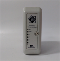
| LED Indicators | OK, RUN, FLT, BUS ACT, Block Status LEDs |
| Software Support | Logicmaster 90-70, Proficy Machine Edition (GSCFG tool) |
| Cable Type | Belden 9841 or equivalent (RS-485 shielded twisted pair) |
| Termination | External DIP switch or terminal resistor required at bus ends |
Product Introduction
The GE IC687BEM742 is the critical communication bridge for Series 90-70 systems utilizing the Genius Bus architecture. It allows a central PLC CPU to control distributed I/O blocks located up to 4,000 feet (1.2 km) away, or even further with repeaters. This module manages the high-speed token-passing protocol, handling data exchange, fault reporting, and block diagnostics automatically.Unlike standard serial modules, the BEM742 offloads the communication processing from the main CPU, ensuring deterministic scan times even with large amounts of distributed I/O. It is essential for legacy systems in power generation, automotive, and heavy manufacturing where Genius blocks are still widely deployed. The “742” revision typically offers improved noise immunity and faster handshake times compared to earlier 740/741 versions.
Installation & Configuration Guide
Phase 1: Preparation (15 min)
Lock out rack power. Plan your Genius bus topology: identify the drop numbers (0–31) for each remote block. Ensure you have the correct shielded twisted-pair cable (Belden 9841). Verify that the first and last devices on the bus will have termination resistors enabled (usually via a DIP switch on the blocks or external terminators). Check the baud rate setting in your software configuration; all devices on the bus must match.Phase 2: Removal (5–10 min)
Disconnect the Genius bus cables from the terminal block or DB connector on the module faceplate. Label cables clearly (Bus A, Bus B if redundant). Note the position of any hardware switches (rarely used for config, mostly software). Loosen captive screws and eject the module. Avoid stressing the backplane connector.Phase 3: Installation (10 min)
Slide the IC687BEM742 into the Series 90-70 rack. It can be placed in any slot, but typically resides near the CPU for easy wiring access. Secure with captive screws. Reconnect the Genius bus wires to the terminals: Data +, Data –, and Shield. Critical: Ensure the shield is grounded at one end only (usually the controller end) to prevent ground loops. Verify termination resistors are active ONLY at the two physical ends of the bus chain.Phase 4: Power-On & Test (15 min)
Restore power. The PWR LED on the rack should be green. On the BEM742:
- OK LED: Should go solid green after self-test.
- RUN LED: Solid green when communicating.
- FLT LED: Off (if no faults).
- Block Status LEDs: Will indicate the status of connected blocks (Green = OK, Red = Fault/Offline).
Connect your programming laptop. Open the Genius Configuration utility (GSCFG) within Proficy or Logicmaster. Perform a “Scan Bus” operation. The software should detect all configured blocks. If blocks show “Offline,” check wiring polarity, termination, and baud rate mismatches.
Troubleshooting Quick Reference
| Symptom | Probability | Action |
|---|---|---|
| FLT LED Solid Red | High | Configuration mismatch or hardware failure. Check if the configured block list matches physical drops. Verify no duplicate drop numbers. |
| Block Status LEDs Flashing Red | High | Communication loss to specific blocks. Check wiring at that specific drop. Verify block power supply. |
| No Communication (All Offline) | Medium | Bus wiring fault. Check Data + / Data – polarity. Ensure termination resistors are present at both ends of the bus. |
| Intermittent Faults | Medium | Noise interference. Check shield grounding (single point). Ensure cable is not running parallel to high-voltage lines. |
| Baud Rate Mismatch | Low | One or more blocks set to different speed. All devices (GBC and Blocks) must be hardware/software set to the same rate. |
Dimensions, Mounting & Wiring Notes
- Dimensions: 1.60″ W × 6.50″ H × 5.90″ D (Single Horizontal Slot)
- Mounting Method: Slides into Series 90-70 universal backplane.
- Terminal Notes:
- Bus Connections: Typically screw terminals or a dedicated connector for RS-485 (A/B or +/-).
- Shield Ground: Dedicated terminal for cable shield. Connect to chassis ground at the controller side only.
- Drop Addressing: Addresses (0-31) are usually set via software configuration or DIP switches on the remote blocks, not typically on the GBC itself (which acts as the master).
- Termination: Critical for signal integrity. Missing termination causes reflections and data errors, especially at higher baud rates.
IC687BEM742 GE
FAQ
Q: Can I mix Genius blocks from different manufacturers?
Generally, no. The Genius Bus is a proprietary protocol owned by GE (Emerson). Only GE Fanuc Genius blocks (IC600, IC610, IC693, IC697 series with Genius interface) are compatible. Third-party gateways exist but require specific configuration.Q: What is the maximum distance for the Genius Bus?
Without repeaters, the maximum distance is approximately 4,000 feet (1.2 km) at lower baud rates (e.g., 93.75 Kbps). At higher speeds (500 Kbps), the distance is limited to ~400 feet. Use Genius Bus Repeaters (IC600CBRxxx) to extend range.Q: Do I need to configure the BEM742 module in the hardware config?
Yes. You must add the IC687BEM742 to your hardware configuration in Logicmaster/Proficy and define the list of expected Genius blocks (by Drop Number and Type). If the physical setup doesn’t match the config, the module will throw faults.Q: Can this module support redundancy?
Yes, the IC687BEM742 supports high-availability redundancy. This requires two BEM742 modules installed in the rack, wired to the same bus, and configured as a redundant pair in the software. If the primary fails, the secondary takes over seamlessly.Q: My block shows “Offline” but has power. What now?
Check the Drop Number setting on the block itself (often rotary switches). Ensure it matches the configuration. Check the wiring polarity (+/-); swapping them will prevent communication. Finally, verify the baud rate switch on the block matches the bus speed.